• The move to the new server is done. There are some software and database maintenance updates in process. This has us passing the hat around to help out. We appreciate any donations. Seriously, even a dollar helps. The payment page may be found here - https://www.audiokarma.org/support.html

Beginning my Sansui AU-919 restoration

f dc offset is not excessive at the moment that the failure occured then you are right on suspecting of a malfunction in the pritection circuit

I am just confused as to why the issue with the protection circuit did not manifest itself until after I re-capped the protection board. I will have to take the back off of the AU-919 and inspect the board to confirm that I did not make any errors, not likely as the process was pretty straightforward. Perhaps the new relay coils have slightly different electrical characteristics that affect how the protection circuit operates? Guess I will find out after I swap out the 2SF656 SCR.
 
I did some additional research and in other threads and they mention TR33 and TR34 on the driver board 2SC1845's cause a lot of problems with protection. The symptoms in the other threads are identical to mine. the AU-919 goes into protection consistently at moderate volume levels.

I have new trimmer pots arriving tomorrow for the driver board that I am going to install to hopefully eliminate the"touchiness" in adjusting the bias and DC offset. While I have the board out I will replace transistors TR33 and TR34 with KSC1845 transistors. If the protection problem goes away that will eliminate the need to disassemble the back panel again to replace the SCR. Once I complete the restoration of the AU-919 I will do full power testing of the unit to determine if I can drive both channels into clipping at 100W or higher at 1KZ. If it goes into protection sooner I will then replace the SCR to see if that eliminates that issue.

Stay Tuned.........
 
On a side note I received Toshiba TTA1943/TTC5200 Transistors today. Read they are potential replacements for the failed outputs with modified mounting. You have to trim one corner to get it to fit the heatsink but these have plastic on the corners so not sure. Will have to file one down and see what that reveals.

Other potential replacements that do have the metal corners are back-ordered until april. Will see how things go till then!

PXL_20251229_223054485.jpg
 
On a side note I received Toshiba TTA1943/TTC5200 Transistors today. Read they are potential replacements for the failed outputs with modified mounting. You have to trim one corner to get it to fit the heatsink but these have plastic on the corners so not sure. Will have to file one down and see what that reveals.

Other potential replacements that do have the metal corners are back-ordered until april. Will see how things go till then!

View attachment 3664712
Those won’t fit , you cannot file the corner .
You will need a TO-3P package.
A good candidate is the complementary pair 2SC3263.
You can read more here :

Good information at Hyperion’s threads regarding restoration of BA-F1 and AU-919.
 
Thanks for replies JoseHH and Sui-Yogi. I ordered T03P transistor replacements for the failed outputs. 2SA223A/2SC6145A. The 2A223AA are obsolete so I ordered 2SA1294A as a substitute which is back-ordered at Digikey till April.

I ordered the Toshiba TTA1943/TTC5200 after seeing them mentioned in a thread, guess I should have looked closer LOL. They may come in handy some day.

I read through the threads you mentioned above and they are quite informative for sure.

Have you considered the pair NJW0281G/NJW0302G ?
I put the quoted transistors in my Digikey Cart just in case. They are back-ordered at Mouser.

On the GOOD news front a fellow AK'r responded to my plea for Original replacements and is sending me an NMC1012 transistor. I already have the NMA1012 transistor so I will have a full set of original output transistors to install when I feel comfortable that the AU-919 is stable. I will install the originals after all the restoration work is done and the AU-919 behaves well for a while afterwards.

Will post more on the results of the TR33 and TR34 replacement on the driver board later today or tomorrow.
 
It is New Years 2026, happy New Year to everyone!

I removed the driver board/heat sink assembly and replaced the four trimmers I previously replaced with 10 turn Trimmers. I also replaced TR33 and TR34 to determine if they were the cause of the protection issue. I then re-installed the assembly and powered up the AU-919 in the DBT. The bulb dimmed normally and I adjusted the bias pots until I saw the bias just start to rise on both channels. I then powered up the unit on the A/ mains and adjusted the bias and DC balance on both channels. The 10 turn trimmers made this process much easier for sure but there was still some sensitivity when zeroing in on 0V DC balance and 20MV bias. I would approach the proper bias point, then overshoot it a bit and when I tried to back down to it the trimmer position seemed to shift a bit. The DC balance behaved similarily. I was able to dial things in but that "touchiness" seemed to still be present. I guess that is the nature of the AU-919.

I then attached speakers to the unit and played some music. I gradually turned up the volume to see if the AU-919 was still going into protection. Unfortunately at about the same point as before protection is triggered so I guess I will be removing the back to access the protection board to replace the SCR. The lead orientation on the replacement are different than on the original so I will double check that I install the replacement correctly. I am still somewhat mystified as to why the protection issue manifested itself after I re-capped the protection board and replaced the relays. I guess the new components somehow affected the operation of the circuit. Should I replace any other components on the protection board while I have it out of the unit?

On a different note, even with the 4Mz. Onsemi transistors installed as outputs the AU-919 sounds amazing. My plan is to restore the Flat Amp F2841 board which is the last remaining board and then replace most of the shielding on the unit. Then I will work on the protection issue and that will complete the restoration.

I will then perform full power testing to determine at what point the AU-919 begins to clip as well as square wave testing through 20KZ to see how well the amp performs with the Onsemi transistors.

Once I am comfortable with the stability of the amp I will re-install the original output transistors, re-set the bias and DC balance and perform the same set of tests to compare the performance of the original VS Onsemi output transistors. It should be an interesting exercise.
 
Tonight I removed the Flat Amp F2841 and worked on it. Removing the board was not too difficult fortunately. There were only four 3PF Black flag capacitors on it which I replaced. The othere either were not present or had been replaced with more reliable substitutes by Sansui. The board had some of that lovely Sansui glue on it but not too bad. The Acetone soak and chopsticks scrape made short work of it. I replaced/upgraded all of the capacitors that were recommended in other threads, the four Zener diodes and the four 2SC1313 transistors that are potential troublemakers. There was a bit of sticky gunk on part of the back of the board which I cleaned off with alchohol. I stopped for the night and will re-install the board tomorroe after a night's rest. Here are a few pictures of the F2841 board:


The board with the Sansui glue:

PXL_20260101_230112105-EDIT.jpg


The board after acetone cleaning:

PXL_20260102_003129013.jpg


The completed board ready to be installed:


PXL_20260102_024402102.jpg
 
This morning I re-installed the F2841 board back into the AU-919. I thought it would be straightforward but no........... An orange jumper wire JP02 was in the way when I tried to push the board into position, no matter how I manipulated the jumper and the board no luck. I was corious how things were situated before I removed the board but that detail was in the shadows in the pictures I took so no insight there. I ended up unsoldering one end of the jumper that was in the way, positioning the board properly and then popping the jumper back in place. A bit tricky popping the jumper back in in the tight space but all worked out well. A picture of the jumper is shown below:


PXL_20260102_143140722.jpg


After soldering the F2841 back in place I plugged the AU-919 into the DBT and powered it up. The bulb dimmed and then brighted a bit and stayed at that level. The amp stayed in protection which seemed odd in that the bias on the left channel was about 1.2 volts so I adjusted the bias down to about 12MV and the unit came out of protection. I set bias on the right channel and DC offset on both channels.

I then brought up the AU-919 to 120V through a variac. I repeated the Bias and DC offset adjustments at full line voltage. I was somewhat surprised that the restored F2841 board caused the bias and DC offset settings to shift so much. The Good news is that both the bias and DC balance adjustments seemed more stable, easier to dial in than before.

I then hooked up a set of speakers and played some music. The amp sounds great but unfortunately the Protection issue persists so I will have to swap the SCR on the protection board as things seem to point to that component as the culprit. The Protection sensitivity I am experiencing during music playback may also explain why the amp stayed in protection initially until I dialed down the bias a bit. I will have to re-read some of the material I found on Audiokarma to better understand the interaction(s) of the protection circuit with the various components it is monitoring.

Next step: SCR replacement.
 
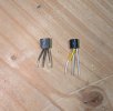
Today/tonight I replaced the 2SF656 SCR on the protection board with the hope that it would remedy the situation with the AU-919 going into protection at relatively moderate volume levels. I used the P0102da_1a33 SCR as recommended by hyperion in several posts. The 2SF656 leads are GAK while the P0102da_1a33 is KGA so I had to GAKify the leads on the P0102da_1a33 to use it. I flipped GA leads on the P0102da_1a33 and installed it in reverse orientation of the 2SF656 and installed it.

Here is a picture of the old and new SCR's :
PXL_20260103_020508657.jpg


Removing the back of the AU-919 was easier the second time. I managed to gain access to the Protection board after unsoldering only the ground wires and disconnecting the power connectors on the other side. After putting everything back together I plugged the AU-919 into the DBT and there were no issues. I then connected it to full line voltage through a variac and confirmed that bias and DC offset were correct.

Then the moment of truth, I connected speakers and a DAC source and played music. The amp played well so I eased up the volume to see if the protection issue was resolved and......... disappointment! :mad: The AU-919 still has the same issue. I also tried enabling the "JUMP" switch to see if that had any effect but it did not, it only moved the point where the AU-919 went into protection further up the volume dial.

At this point I am not sure now to proceed, the first step would seem to be to determine what specific event/issue is triggering the protection event. In the past I did not see any sudden shift in bias or DC offset when the AU-919 went into protection. Since all of the boards in the AU-919 have been restored I will perform all of the many adjustments to confirm everything is up to specifications in case something amiss there is causing any issues.

I also plan on separating the power amp on the AU-919 and driving it from another source, in this case it will be the pre-amp section of a Rotel RA-1312 that have restored previously to see if the AU-919 goes into protection when only the power amp is driven. If it does then I will know that the issue is in the protection/power amp compination of components.

I will post more as I proceed........

 
This morning I did some further testing to try and isolate the problem with the AU-919. I verified that all of the adjustment settings on the AU-919 were correct. T them monitored bias and DC offset on both channels while adjusting the volume to trigger protection. I did not detect any anomaly in either the bias or DC offset that would be triggering protection on the AU-919.

I then put the Rotel RA-1312 on the bench put it in "separate" mode and used it's preamp section to drive the power amp in the AU-919. This arrangement played well until I advanced the volume on the Rotel to a moderate volume level at which point the AU-919 went into protection just as it did when using the built-in pre-amp.

It looks like the issue is in the interaction between the driver/output sections of the AU-919 and the Protection board. I stated earlier that this protection issue did not occur until I re-capped the Protection board and replaced the relays. Everything looked in order when I inspected the Protection board but I must have missed something apparantly. Hate to do it but I will have to again remove the rear panel and confirm that I did not make an error when I re-capped the protection board.

I am tempted to replace some of the transistors on the Protection board to eliminate them as a potential issue but will ponder things further before proceeding.

Maybe it is a good idea to take a day or two off to clear my head.:crazy:

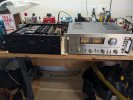
Here is a picture of both units on the bench. On another note the sound of the AU-919 power amp when being driven by the Rotel pre-amp is different, not "bad" but something subtle is missing. I will have to try driving the Rotel Power amp with the AU-919 pre-amp to compare the sound.

Here is a picture of both units on the bench:

PXL_20260103_155854396.jpg
 
@richiem46 , take a look at post 28 & 29 of the below thread if you haven't already done so. Could be TR33 or TR34 on power amp board:


Also, if you have any before and after pics of the protection board maybe you should post them to see if more eyes on the work spot something you may have missed.
 
Vintagear, thanks for the referencing the thread above. I came upon it before and based on what I read I replaced TR33 and TR34 prior to replacing the SCR on the protection board.

Re-reading post #28 gave me an idea, I connected the speakers and AUX input back to the AU-919 and played music through it. As before, it went into protection mode at a moderate volume level. I then removed the left channel AUX input and played music again. With only the right channel driven the AU-919 went into protection at the same point on the volume control. I repeated the same test with only the left channel driven and low and behold, no protection was tripped. I turned up the volume to practically the threshold of ear pain and still no protection! Progress!

I will focus on the right channel section of the Driver board as that is the source of the protection fault.

Thanks for your post as it made me revisit the Protection post and gain new insight into the issue.

And am glad I will not be dismantling the rear panel to gain access to that Protection board!
 
Vintagear, thanks for the referencing the thread above. I came upon it before and based on what I read I replaced TR33 and TR34 prior to replacing the SCR on the protection board.

Re-reading post #28 gave me an idea, I connected the speakers and AUX input back to the AU-919 and played music through it. As before, it went into protection mode at a moderate volume level. I then removed the left channel AUX input and played music again. With only the right channel driven the AU-919 went into protection at the same point on the volume control. I repeated the same test with only the left channel driven and low and behold, no protection was tripped. I turned up the volume to practically the threshold of ear pain and still no protection! Progress!

I will focus on the right channel section of the Driver board as that is the source of the protection fault.

Thanks for your post as it made me revisit the Protection post and gain new insight into the issue.

And am glad I will not be dismantling the rear panel to gain access to that Protection board!

Great to hear that you now have the issue isolated to one channel. One more thing, since I think you said the problem only started after you worked on the protection board, carefully check all connections going to the driver board. It's possible you disturbed something when manipulating the protection board. Check voltages on DB if possible.
 
Worth checking at the protector board
R3-R4 10Ω/2W (R3 right channel) , if it’s open?
If I’m not mistaken you can reach there from the bottom or top with out removing the back plate ;
 
Worth checking at the protector board
R3-R4 10Ω/2W (R3 right channel) , if it’s open?
If I’m not mistaken you can reach there from the bottom or top with out removing the back plate ;

Sui-Yogi, I just checked R3 and R4, they both read about 21 ohms in-circuit, not at specification but not open. I can't see the color bands on them to determine if there was a deliberate change made when assembling the unit.

Will keep looking, eventually I will come across the issue I am sure.
 
I am looking at the schematic and am confused.

1767545084833.png


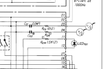
Here is a snippet of the protection board schematic with R03/R04 shown. The circle with U/2 implies to me that positions 3 and 4 are connected to some common point somewhere in the Driver/output section. I looked there and everywhere else and I cannot find where 3 and 4 connect to. I could have missed it somehow but cannot find the corresponding connection points.

Can anyone provide insight into my eyesight issue?

Thanks!
 
I am looking at the schematic and am confused.

View attachment 3668764


Here is a snippet of the protection board schematic with R03/R04 shown. The circle with U/2 implies to me that positions 3 and 4 are connected to some common point somewhere in the Driver/output section. I looked there and everywhere else and I cannot find where 3 and 4 connect to. I could have missed it somehow but cannot find the corresponding connection points.

Can anyone provide insight into my eyesight issue?

Thanks!

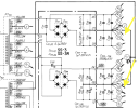
Look for U/1 on the Power Supply section (F-2845) on the schema. See yellow arrows below. Location is Grid section D1.
1767546957083.png
 
Last edited:
Look for U/1 on the Power Supply section (F-2845) on the schema. Grid section D1.


Thanks Vintagear, I should have paged down! So it looks like the protection board is monitoring the two power supplies for a failure. Since the monitor is passing through a .047 capacitor I am assuming it is monitoring for ripple or A/C.

On another note I put a meter on Pin# 20 on the protection board to monitor it for some sort of voltage event that might trigger protection. When the AU-919 was running normally the meter read .5 MV. When it went into protection it dropped to .1MV. Once it came out of protection it went back to .5MV. Doesn't seem like a triggering event to me but this is some guesswork on my part.

I also monitored DC offset from the driver board for each channel to see if there was an anomaly. Both channels looked normal until protection was triggered at which point the DC offset moved around a bit, maybe to 40-50MV and then settled right down after the amp came out of protection.

So far no luck trying to identify what event is triggering protection........
 
Back
Top Bottom