• The move to the new server is done. There are some software and database maintenance updates in process. This has us passing the hat around to help out. We appreciate any donations. Seriously, even a dollar helps. The payment page may be found here - https://www.audiokarma.org/support.html

Beginning my Sansui AU-919 restoration

After taking some time away to ponder the protection situation I thought about my previous post regarding Pin #20 on the protection board. I realized that the meter would indicate a DC voltage event which was probably the wrong approach. I then hooked up my ocilloscope to Pin#20 on the protection board with the negative lead to chassis gnd. The scope was picking up all sorts of extraneous noise, probably because of the long ground connection.

I set the probe to 10X and played some music through the AU-919. As before, when I reached a certain volume level it went into protection and I did not see anything on the scope, though through the noise I probably missed something I am sure. I tried a few more times without success in discerning any event on the scope and then set the probe to 1X. I then advanced the volume and.......... no protection triggered:crazy:. I unplugged the probe from the scope but left it connected to the AU-919 to see if being connected to the scope affected things in any way and low and behold, no protection triggered. I then disconnected the probe completely and...............no protection triggered.

Interesting set of events, I thought that perhaps there was a thermal efect as the AU-919 was on for a while and power-cycled many times during the test. I let it play for about an hour and then turned it off and made dinner for us. I just went out to the garage at 8pm and powered the AU-919 back up and turned up the volume and.... no protection, it did flutter once at high volume but after that it played fine.

So now I think I have a thermal issue somewhere in the protection board or the right channel. I will leave the unit off over night and then see how it behaves in the morning. If it goes into protection I will leave it playing at a moderate volume level to warm up thoroughly and then try turning the volume up to see if protection is tripped or not to confirm the issue is thermal. Then all I have to do is see what component is the culprit.........
 
After taking some time away to ponder the protection situation I thought about my previous post regarding Pin #20 on the protection board. I realized that the meter would indicate a DC voltage event which was probably the wrong approach. I then hooked up my ocilloscope to Pin#20 on the protection board with the negative lead to chassis gnd. The scope was picking up all sorts of extraneous noise, probably because of the long ground connection.

I set the probe to 10X and played some music through the AU-919. As before, when I reached a certain volume level it went into protection and I did not see anything on the scope, though through the noise I probably missed something I am sure. I tried a few more times without success in discerning any event on the scope and then set the probe to 1X. I then advanced the volume and.......... no protection triggered:crazy:. I unplugged the probe from the scope but left it connected to the AU-919 to see if being connected to the scope affected things in any way and low and behold, no protection triggered. I then disconnected the probe completely and...............no protection triggered.

Interesting set of events, I thought that perhaps there was a thermal efect as the AU-919 was on for a while and power-cycled many times during the test. I let it play for about an hour and then turned it off and made dinner for us. I just went out to the garage at 8pm and powered the AU-919 back up and turned up the volume and.... no protection, it did flutter once at high volume but after that it played fine.

So now I think I have a thermal issue somewhere in the protection board or the right channel. I will leave the unit off over night and then see how it behaves in the morning. If it goes into protection I will leave it playing at a moderate volume level to warm up thoroughly and then try turning the volume up to see if protection is tripped or not to confirm the issue is thermal. Then all I have to do is see what component is the culprit.........
Reinspect your work for cold solder joints.
 
I assume I should focus on the Driver board Right channel as that is the channel that triggers protection when driven separately.

Thanks for your help.
I’d say the right channel path on any board you touched or worked on since before the protection issue started.
 
As an update, the next morning after my last post the AU-919 is back to the original failure mode which is that at moderate volume level it goes into protection.

I spent Tuesday afternoon and evening looking over the schematics of the AU-919 trying to gain some insight as to what in the right channel was triggering protection. Since the same failure mode occurred when I drove the AU-919 from another pre-amp, this indicated that the issue is in the right driver board or the protection board. Up until this point I kind of focused on events propagated from pin #31 on the driver board to pin #20 on the protection board.

Based on the experience of other AK'rs and my own instincts I replaced transistors TR33 and TR34 and then the SCR 2SF656. The problem persisted. I then experienced the strange phenomenon of intermittent failure then correct operation, then failure again while attaching my scope to pin #20 on the Protection board.

I poured over the schematics of the driver board and the protection board trying to gain further understanding into how the protection circuit interacted with the other components of the AU-919. I contemplated which additional components might be causing issues with protection on the driver board and made a list of potential components to test/replace.

While looking over the protection board I observed that bi-polar Capacitors C03 and C04 were attached to the left and right speaker inputs separately and then though diodes to the rest of the protection circuitry. As I stated earlier, there was no protection issue until I re-capped the protection board. I reviewed the board when I had it out to replace the 2SF656 SCR and things looked good.

So last night I went back out to the garage to take a look at C03 and C04. I used a flashlight to view the underside of the protection board and then wobbled each capacitor slightly with my finger (very scientific!) to see if was seated/soldered securely. One was but the other wobbled a bit and I could see that while the connecting wire was surrounded by solder it was moving in and out, not making good contact with the protection board foil, cold solder joint. (Vintagear, you were correct!) Today I re-soldered the joint and low and behold, no more protection failure! A rookie mistake but it happens even to us Geezers.

It also explains the odd behavior with the scope probe on Pin #20 on the protection board. The probe probably shifted the board just enough when I manipulated it to cause the cold connection to work temporarily and then revert to failure mode once things settled down again. It was a frustrating but excellent learning experience and now I can move forward with final testing.

Thanks again for everyone's help on this!
 
So last night I went back out to the garage to take a look at C03 and C04. I used a flashlight to view the underside of the protection board and then wobbled each capacitor slightly with my finger (very scientific!) to see if was seated/soldered securely. One was but the other wobbled a bit and I could see that while the connecting wire was surrounded by solder it was moving in and out, not making good contact with the protection board foil, cold solder joint. (Vintagear, you were correct!) Today I re-soldered the joint and low and behold, no more protection failure! A rookie mistake but it happens even to us Geezers.

Excellent news! Glad I was able to help you out with the protection issue.
 
Last edited:
Yesterday I did some full power testing on the AU-919 to determine if it was performing at it’s full potential. I attached the speaker outputs to an 8-ohm 100W non-inductive load and connected my signal generator to the AUX inputs and let it warm up a bit.

I started with the left channel driven only. I applied a 1Kh. signal and monitored the left speaker output with my scope. I chose the left channel first as it was the one that failed mysteriously earlier. I gradually increased the volume on the AU-919 being cautious due to the previous output failure. At just about 30V RMS the output started to clip which translates into about 110 Watts RMS which I thought was pretty respectable.

I performed the same test on the right channel and achieved the same results which I was also pleased with. I then repeated the same test driving both channels with the same results, not surprising given the dual output power supplies in the AU-919.

I then configured the test setup so that the speaker output on both channels was about 20.2V which translates to about 50 watts per channel at 1 Kz. All tone controls were bypassed as they were in the previous tests. I chose 50 watts arbitrarily as it was half the rated output of the AU-919. I then varied the input frequency to 5Kz, 10Kz, 15Kz and then 20Kz to see how linear the AU-919 was. The final output voltage at 20Kz was 19.94V which is a difference of only .26V or about ½ watt frpm the reading at 1Kz.
I thought these numbers were quite good and demonstrate that the AU-919 is very linear over the audio spectrum.
 
Last edited:
On a different note, I read a series of papers from Karmon Kardon about using Square Waves Analysis to measure potential Audio Amplifier Performance. The paper is from 1975 and of course touts the superior performance of some HK units to their competitors. It uses an amplifiers accuracy at re-producing square waves at various frequencies as an indicator of better performance. It was posted on AK in 2007 by member GeneT. Here is a link to the post for anyone who is interested in reading it:


What I tried to do was to apply the same square waves to the AU-919 as were done in the HK analysis to see how it compared to the results presented in the HK analysis. It seemed like a good way to see how “fast” the AU-919 is with the MJE outputs installed.

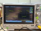
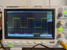
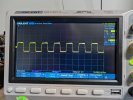
In the first test I applied a 20Hz square wave to both AUX inputs and monitored the speaker output with the 8-ohm non-reactive load as suggested in the HK write-up. The RMS voltage across the output was 6.73V RMS which translates to about 16 watts. The HK analysis states the percentage of “tilt” in this display indicates the potential performance of the amp at lower frequencies. You can read the particulars in the analysis. I did not calculate the tilt but it looks like the AU-919 doesn’t look too bad in this regard compared to some of KH's "competitors". The scope output for the 20Hz test is shown in the picture below:

PXL_20260110_194808631.jpg
 
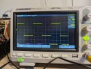
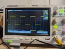
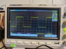
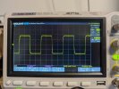
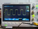
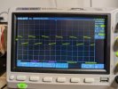
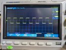
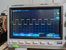
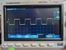
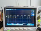
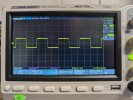
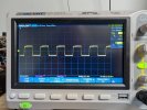
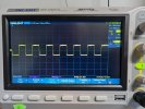
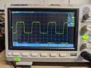
I then repeated the test at 1Kz, 5Kz, 10Kz, 15Kz, 20Kz, 25Kz and 30Kz to see how the AU-919 performed handling square waves at various frequencies. The first thing I noticed is that the RMS voltage rose to about 8.5V RMS for these tests, up from 6.73V in the 20Hz test. From what I saw the AU-919 performed pretty well overall in this test. There are some Rounded Corners on the square waves at the higher frequencies but overall, not too bad with the 4Mz MJE outputs installed.

1Kz
PXL_20260110_194913872.jpg

5Kz
PXL_20260110_194939756.jpg

10Kz

PXL_20260110_195007692.jpg

15Kz

PXL_20260110_195042423.jpg

20Kz

PXL_20260110_195105260.jpg

25Kz

PXL_20260110_195127320.jpg\

30Kz

PXL_20260110_195205059.jpg
 
I am making an assumption here that the MJE output transistors are affecting the square wave traces because they are slower devices than the original Sansui transistors. To test this theory I decided to re-run the above test after uncoupling the pre-amp from the power amp in the AU-919 and then monitoring the pre-amp output on the scope. Here are the same series of traces from the pre-amp output. They are slightly cleaner but the difference is not startling. It makes me wonder what improvement installing the original Sansui outputs will make. This is all assuming this analysis is relevant one as far as determining the potential performance of a given amplifier.

Thoughts?

20Hz.

PXL_20260110_043307986.jpg

1Kz

PXL_20260110_043433267.jpg

5Kz
PXL_20260110_043516434.jpg

10Kz

PXL_20260110_043549682.jpg

15Kz
PXL_20260110_043615581.jpg

20Kz
PXL_20260110_043647758.jpg

25Kz
PXL_20260110_043713450.jpg
 
It makes me wonder what improvement installing the original Sansui outputs will make.

Thoughts?

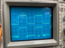
You may have to increase the frequency to possibly see a more noticeable difference between square waves of a conventional vs "high ft" output. I can't speak to the MJs vs the original outputs in the 919 but if you still have MJs in there you can try to set your parameters as below to see how they compare to the outputs in another high bandwidth Sansui amp as seen below.

50kHz 5 µs square wave @Aud10file took of my AU-X1 on his scope a few years back:

1768414729680.png

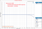
I also have another amp that has modern Sanken T03P outputs that I chose to match the specs of the original high speed T03 Sankens in the X1. The square wave looked just like the pics above and below is how it measured on Amir's Audio Precision Analyzer over at Audio Science Review. As expected, high speed drivers and outputs that produce clean square waves at higher frequencies will also have a superb off the charts frequency response (and vice versa). Below image, flat as a rail and @200kHz still only ~-1dB.

Whether it's overkill is not the point, but it is what the engineers at the time were designing for based on their theories.

1768415792813.png
 
Last edited:
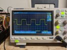
Today I hooked up the AU-919 speaker outputs to the 8 ohm non-reactive loads and applied a 50Kz signal to both the left and right inputs. I drove the amp to 12V RMS which is about 18 watts per channel. I set the scope to 5us sweep and connected it to the right channel speaker output. A picture of the resultant output is below:

PXL_20260115_163143536.jpg


Looks pretty similar to the AU-X1 trace Aud10file took a few years back. The MJE transistors seem to be holding their own.....
 
Since I replaced both the output transistors and the drivers in the left channel with Onsemi's I took the same trace on the left channel to see of the new driver transistors had any negative effect. A picture of that trace is shown below:

PXL_20260115_210900242.jpg


It looks pretty much the same as the trace on the right channel.
 
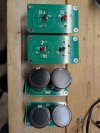
While I am waiting for the NMC1012 transistor to arrive I assembled replacements for the four 15,000 mf oval filter capacitors. They consist of two 10,000uf 63V capacitors connected in parallel. My plan when the NMC1012 transistor arrives is to replace the Onsemi output transistors with the original high-speed Sansui transistors and then to repeat all of the tests done in the previous posts. This will provide as comparison between the performance of the AU-919 with the Onsemi outputs Vs. the original Sansui outputs.

Once this testing is completed I will replace the oval filter caps with the assembled replacements. This will be relatively easy in that everything just unscrews and re-screws in, no soldering required. I will them repeat the above tests though I doubt replacing the oval filter caps will affect the frequenct tests. I am curious to see if the clipping point of the AU-919 will be a bit higher with the replacement filter caps and how the amp sounds sonically.

Based on the combined results I will then decide on which set of filter caps I will leave in place. For esthetics I know most prefer the vintage look of the oval caps. If overall performance is improved noticeably with the replacement caps I may decide to bite the bullit and re-stuff the ovals to maintain appearances. If the performance gain is negligible I may just re-install the original ovals and call it a completed restoration. Will wait and see.......
Here is a picture of the assembled filter replacements:

PXL_20260117_041714806.jpg
 
Last edited:
The NMC1012 transistor arrived today which pleased me! I tested it and it tested good. I removed the driver/output assembly and re-installed the 6 original outputs and the two replacements. Things went smoothly, I re-installed the driver/output board and I powered up the AU-919 and the bulb dimmed as expected and then becane a bit brighter. I dialed back the bias on the right channel and the bulb dimmed and the AU-919 came out of protection. I then gradually applied line voltage via a variac until full line voltage was reached. I then set bias and DC offset on both channels without difficulty.

I then hooked up the speakers and listened to some music for a while. The AU-919 sounds great, if there is a difference in how it sounds with the original outputs installed it is a very subtle one. It is too late to start tonight but tomorrow I will go through the same series of tests I did previously with the Onsemi outputs after I first determine the clipping point of both channels at 1Kz.

Here is a picture of theDriver/output board with the Original outputs installed.

PXL_20260121_021529919.jpg
 
I decided I would perform all of the frequency-related tests on the AU-919 before I did the full power clipping test just in case the full power test caused a failure. This way I would at least have the comparison data between the two sets of output transistors.

The first test I performed was to apply the 20Hz square wave signal and monitored the speaker output. Again I did not calculate the percentage ofof “tilt” in the display but the scope trace did not appear significantly different from the one I took with the Onsemi outputs.

Here is a picture of the 20Hz trace:

PXL_20260121_215304603.jpg

I will post the rest of the test results after dinner.
 
The next Series of tests I did was to input square wave signals at various frequencies to see how well the AU-919 handles them with the original output transistors. what I observed was that from 1Kz through 25Kz and even at 50Kz the traces I took were pretty much the same as the ones I took in the previous tests with the Onsemi Output transistors.

Here are the photos of the traces at 1Kz through 25Kz.:


1Kz

PXL_20260121_215701060.jpg

5Kz:
PXL_20260121_215725582.jpg

10Kz:
PXL_20260121_215749766.jpg

15Kz:
PXL_20260121_215829025.jpg

20Kz:
PXL_20260121_215843504.jpg

25Kz:
PXL_20260121_215911863.jpg


Here is the final trace at 50Kz. Ahain, it is not apprecialby different of the trace taken with the Onsemi outputs.

PXL_20260121_220231324.jpg


Based on my measurements there is no appreciable difference between the square wave traces using the Onsemi VS the original Sansui transistors in the output stage of the AU-919. The baseline assumption here is that these tests are, in fact an indicator of how an amplifier will perform when reproducing complex musical waveforms.


I listened to the AU-919 for about an hour last night and it did seem subtly different somehow, hard to quantify, but different. Then again, the power of suggestion comes into play I suppose. I do not pretend to be an audiophile but I have listened to a lot of different amplifiers over the last several years and the AU-919 is one of the nicest I have heard. The one that comes closest to my ears is the Rotel RA-1412 I restored and use in our house in Michigan to listen to vinyl. I use the Rotel with the tone controls disabled and no loudness contour. I find that with the Rotel you do not need any tonal adjustments, in that sense it reminds me of the AU-919. I will have to try the above tests on the Rotel when we go back north for the summer.
 

Attachments

  • PXL_20260121_215936028.jpg
    PXL_20260121_215936028.jpg
    114.7 KB · Views: 1
Last edited:
The last series of tests I performed on the AU-919 were the full power/clipping test and the frequency Linearity test. As I stated earlier, I waited to perform these tests last as I was a bit Failure-shy after a pair of the original Sansui transistors failed during a routine bias adjustment earlier on.

I applied a 1Kz. signal to the Aux ports of both channels and attached 8 ohm non-reactive loads to the speaker outputs and monitored the right speaker output with my scope. I gradually increased the volume on the AU-919 being cautious due to the previous output failure. At just about 30V RMS the output started to clip which translates into about 110 Watts RMS which was virtually identical to the results achieved with the Onsemi outputs. I tested the left channel and achieved similar results. Both sets of tests were done with both channels driven. The Sansui outputs did seem to run a bit hotter than the Onsemi's but not alarmingly so. Perhaps that is due to the higher current rating of the Onsemi's.

I then configured the test setup so that the speaker output on both channels was about 20.19V which translates to about 50 watts per channel at 1 Kz. All tone controls were bypassed as they were in the previous tests. As in the previous test with the Onsemi outputs I chose 50 watts arbitrarily as it was half the rated output of the AU-919. I then varied the input frequency to 5Kz, 10Kz, 15Kz and then 20Kz to see how linear the AU-919 was. The final output voltage at 20Kz was 20.15V which is a difference of only .04V which is negligible. It seems that the Sansui outputs are just a bit more linear than the Onsemi's but the difference is so small as to be inaudible.

I am not sure what ultimate conclusions to draw from what I have observed with these tests. I guess one take away is that folks that had to replace the original Sansui outputs with Onsemi's should take heart :) .

I will, of course, leave the Sansui outputs installed. My next task is to re-wrap the wiring harnesses that I un-wrapped to gain access to the various boards and components during the restoration process. After that, I will install the new main filter cap assemblies I assembled the other evening to see how they affect the AU-919's clipping point and also sonically as I mentioned previously.

I thank everyone who helped me with this restoration. All your help was really appreciated!

Rich
 
Thanks for taking the time to share these results. Either way, it looks like you have a very healthy 919.

It's probably inconsequential, but if you compare the square waves past 10kHz you can actually start seeing the rounding of the transitions on the SW edges of the Onsemi replacements. The transitions with the original outputs are almost 90°, very sharp. You can also see that the rise and fall time of the wave has more of a slope on the Onsemi outputs vs. the original outputs. Even at 20kHz you can see that the rise and fall are almost vertical and the corners are not rounded on the originals like with the Onsemi outputs. Again, possibly meaningless but very cool to visualize the comparison on a scope. Maybe it's the camera angle but that's how it appears to me when I click back and forth between the images you posted.
 
Last edited:
Back
Top Bottom