• The move to the new server is done. There are some software and database maintenance updates in process. This has us passing the hat around to help out. We appreciate any donations. Seriously, even a dollar helps. The payment page may be found here - https://www.audiokarma.org/support.html

Beginning my Sansui AU-919 restoration

It’s been a while since I restored my AU-907Limited but I do remember that the wise move is to remove the back panel.

Unscrew the feet from the bottom cover and screw them directly to the cassis with out the bottom cover so the amp stays elevated.

You will need to cut of the power/Switch/wires coming in from the plug and unsolder the GRN (turntable)wire that goes to the RCA pcb. After, simply take a lot of pictures and mark what you unsolder until you have the back plate free from the chassis.

Extra careful with the speakers wires , better cut off rather unsolder as you might lift the traces .

If you need pictures I can find some and forward it here .

Good luck!


That is a good idea, removing the back panel, will provide access to several boards that need some work done on them. I will take a look at the specifics on my AU-919 and decide how to proceed.

Thanks Sui-Yogi!
 
On another note, I received the boards used to replace the four oval main filter capacitors. As I mentioned in a previous post I will leave to the end of my restoration the decision weather or not to replace/re-stuff the mail filter capacitors. It occured to me that I can build out the boards with the capacitors I already have for the re-stuff and have them ready.
I can do full power testing to determine when the AU-919 begins to clip with the original oval caps and then listen to the AU-919 for a while. I can then just unscrew the connectors and clamps on the oval capacitors and replace them with the board replacement units . Pretty straightforward. I can then re-test to see if the clipping point changes with the replacement caps installed and then listen to the AU-919 for a while with the new caps to see if there is a noticable change in how the unit sounds. If the sound of the amp is noticeably improved and/or the clipping point I can then use the same caps mounted on the replacement boards to re-stuff the oval cans. If the performance is not noticeably impacted I can just leave the original oval caps in place and eliminate the re-stuffing process.

Here is a picture of the boards I received today.

PXL_20251205_004237551.jpg
 
... Things went pretty well thoufg I wish I had a higher wattage soldering gun to solder all of the power connections in ....
I know I'm quoting a post from the previous page, but yeah i recently upgraded to an old weller model. Something similar to this (picture from google.

1764900477806.png

A local ex engineer was selling NOS for super cheap. It worked superbly well, really REALLY made working more pleasant.
The only thing happened was a few days into using it the temperature slider broke because the plastic holding the neck had gotten brittle over time. The slider pot is an uncommon 1k ohm value and there were no replacements available locally so i used the wipers from a different slider to fix it.

been doing other stuff since and it feels very good. its rated between 40-60 watts I reckon. heats up ground planes really fast.
 
Today after completing the refurbishment of the boards that I detailed above I decided to power up the AU-919 on a dim bulb tester to see where things stood. I had a 60W bulb installed in the DBT initially and the bulb got bright and then dimmed as expected. I attempted to measure the bias voltage but read 0V on both channels refardless of the setting of the two bias adjustment pots. I then substituted a 72W bulb which is the largest I have on-hand. I was then able to detect bias voltage which I then set to zero for the moment. All seemed to be well so I plugged the AU-919 into a variac and gradually eased the voltage up to 120V. I was then able to set the bias to 20MV for both channels per the manual and things seemed to be stable. As the AU-919 still is in protection I was unable to set the DC offset.

The AU-919 still stays in protection which was the original issues so I am assuming there is some issue with the protection board itself. Since accessing the protection board entails desassembling the rear panel I plan to re-cap the protection board and also replace most of the transistors on the board.

I will replace the five 2SC945 transistors with KSC945CYTA transistors. The 2SD438 transistor with a KSC2690 and the 2SF656 SCR with a 2N5062.

I will test the old transistors as I remove them to see if they are faulty. Kind of a wholesale replacement but I am hoping to avoid multiple iterations of removing and servicing the protection board. I am quite pleased with how things have gone thus far and hope once I refurbish the protection board it will come out of protection.

I am leaving town for 6 days so I am not sure how much I will get done until I return.

Stay tuned........
 
The AU-919 still stays in protection which was the original issues so I am assuming there is some issue with the protection board itself. Since accessing the protection board entails desassembling the rear panel I plan to re-cap the protection board and also replace most of the transistors on the board.

I will replace the five 2SC945 transistors with KSC945CYTA transistors. The 2SD438 transistor with a KSC2690 and the 2SF656 SCR with a 2N5062.
Hello,
You can adjust the dc offset directly at the wires that come out of the power amplifier ( white and blue wires 27 and 28 at the edge of the F2839 board). There you can see the DC offset even if the relays do not engage. It is best to do this before changing all the components in the protection circuit.

I understand, I can measure DC offset between pins 27 and 28 and the corresponding negative speaker terminal to measure the DC offset bypassing the relay. Looks like I could also measure the offset from pins 1 and 2 on the protection board as these are the destination points of the white and blue wires but access to those connection points is limited so I will go with #27 and #28 and report back.

Thanks for your suggestion!
 
I went to set the DC offset on the left channel using the method JoseHH suggested and the offset on the left channel was 2.5V which is clearly too high. I adjusted the trimmer for that channel and brought the offset down to a few millivolts. Getting it to zero proved challenging with the trim pot. I should have gotten the bournes 10-turn trimmer but I digress.....

Once the DC offset was set to a reasonable level I heard a "click" which was the AU-919 coming out of protection. :jump:

I set the DC offset on the right channel which was about .5V before I set it.

I hooked up a pair of JBL 100T3 speakers to the amp to have a listen. The amp plays well, the soundstage is really quite striking, even at this point in the restoration. Initially I thought the amp sounded kind of flat but I guess I am more used to the Loudness button than I thought. What others have said about the AU-919 is true, it does not impose any sonic signature on the source material. On things like Steely Dan, Joey di-francesco and Van Morrision, Lyle Lovit's hits etc. the AU-919 blows me away. On other recordings it sound a bit thin due to the nature of the source material I guess.

I will still re-cap the protection board and replace the relays and also, the Tone board when I return from visiting family up north to complete the restoration.
 
Another update, on the 2835 board that I completely restored there are two center DC adjustment pots VR01 and VR02 which I had not adjusted until this evening. The voltage was way off, like 1.5v on both the right and left channels rather than zero. I adjusted both channels to as close to zero as I could dial in. Again, like the bias and DC offset settings, these settings were VERY sensitive.

After adjusting these settings the AU-919 played stronger, the material I thought sounded thin sounded much better, I will listen a bit more tomorrow while packing for our trip but I am much more pleased with the sound of the AU-919 after adjusting these settings.
 
I returned from visiting family several days ago, always nice to see the grandchildren!

I listened to the AU-919 when I returned and it was playing beautifully. Last night I decided to check the bias to see if it had drifted. The left channel was a little low and I touched it up. I then went to adjust the right channel and it was a bit low also. I was adjusting the right channel, the bias was very erratic, I was having trouble dialing it in when there was a pop and the AU-919 powered down.

I checked and the main 10A fuse had blown.........

I did not have a 10A replacement so I installed an 8A replacement and plugged the AU-919 into the dim bulb tester and powered it on. The bulb lit up brightly which implies a dead short somewhere, I suspect in the right channel. Holidays permitting I will have to check that channel to see what component has failed. I suspect one of the outputs failed but am surprised at what happened. Checking/adjusting the bias should not trigger a catastrophic event.

Interested in any insight into these events.

Hopefully if an output failed it is one I have a replacement for.
 
I did some prelimimary testing today and it looks like two outputs on the LEFT channel are shorted which is interesting in that I was adjusting bias on the right channel when the failure occured. The right channel bias was dialed in cirrectly.

I will know more when I get to removing the output transistors entirely and testing them. Just so strange for the channel to fail so suddenly after playing well for several days.
 
Last edited:
I had the same problem when I restored my AU-907 , same symptoms . Fortunately I did not blow up the outputs as I was very concerned and cautious with a small fluctuation I had at the bias (flat amp and power amp) so I never took it of the bench.
The fluctuation was small and everyone would suggest that this can be “normal”.
After investigation I found that I have mistakenly replaced the black flags on the flat amp (solder side of PCB) and solder the new capacitors wrong (solder bridge is possible too ) .
Example : instead of connecting the 3P cap on the TR09 between the base and collector , I soldered it between the collector and emitter . The Transistor was blown but I could still adjust bias (radical but well within the normal limits) and I could hear music just fine;

Worth checking your work at the flat amp, the above it’s my personal experience, it can be hundred other possibilities of what happened in your amp …. for example : the screwdriver you are using to adjust bias , is it metallic or plastic/no conductive ? You can easily touch or create an arch between two components and short the circuit …..
 
Thanks for your comments Sui-Yogi, I will review my work to be sure all the restoration done to date is correct. I used a plastic screwdriver to adjust the bias pots as i have had negative experiences in the distant past using metal tools!

I am looking at potentially using T03P transistor replacements for the failed outputs if it comes to that. 2SA223A/2SC6145A. The 2A223AA are obsolete so I ordered 2SA1294A as a substitute which is back-ordered at Digikey till April. Will see how things go.

While waiting for the T03P parts I will install the MJE21193/94 4MZ T03 transistors so I can move forward.

Turning into more of an adventure that I thought it would!o_O
 
I removed the power amp board and tested the output transistors. One pair tested fine and the other pair were both shorted, one witl all of the leads shorted together.

Here are pictures of the tests........ I will replace all of the outputs on both channels with Onsemi 21193/94 transistors and go on from there.


PXL_20251220_214906279.jpg

PXL_20251220_214957569.jpg
 
I replace all of the original Sansui output transistors with the Onsemi 93/94 outputs. I checked the driver transistors in the failing channel and sure ehough, they were damaged also. I will replace them with 2sd382 = MJE15030 ON-Semi, 2sb537 = MJE15031 ON-Semi as recommended in several threads. They are 30MZ devices which should preserve the high-bandwidth characterisitcs of the AU-919 when I replace the Onsemi 93/94 outputs with higher bandwith devices.

Here is a picture of the heat sink with the Onsemi putputs installed:

PXL_20251221_003008455.jpg
 
Last edited:
The replacement driver transistors MJE15030/MJE15031 shipped today from Mouser and will arrive on Dec 29th. I was hoping to get then before Christmas but guess the next setp(s) will have to wait. I also ordered multi-turn Pots for the driver board which hopefully will make dialing in the bias and DC offset a little less "touchy".
 
The mouser order arrived early today at about 1PM so what else would one do on Christmas Eve but work in the garage on an AU-919! I replaced the failing driver transistor and it's compliment with the MJE15030/MJE15031 Onsemi transistors. I plugged the amp into the dead bulb tester and powered it up. The bulb brightened and then dimmed and then pulsed bright and then dim. Interesting behavior, the amp exhibited the same behavior with all of the original transistors installed. I adjusted the bias pot on the left channel and the amp settled down and the bulb remained dim, the same way I did with all of the original transistors installed.

Does anyone have any insight into the "pulsing" behavior? The left channel bias adjustment was complicit in both cases.

Anyway, the AU-919 is playing beautifully again. Unfortunately I ordered the wrong Bournes bias/balance pots so I will read through the AU-919 threads to find a recommendation for a suitable replacement. The ones I installed from the kit are just too "touchy" and may indeed be a potential source of the left channel failure.

With that, Merry Christmas!
 
Last edited:
Pulsing is because the bias value is too high and high load drops the DBT voltage too much, so the bias stops flowing altogether, then when with no load DBT has voltage again, bias flows again and the cycle continues until the bias value is adjusted not to overwhelm the DBT.
 
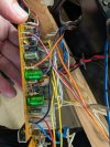
While waiting for the teplacement trimmers for the driver board I followed Sui-Yogi's advice and removved the back panel of the AU-919. After studying things for a while I realized that most of the rear panel components could be unscrewed and only a few connections need be unsoldered to gain access to several boards that needed attention for the restoration process as SUI-Yogi had pointed out. Here is apiccture of the amp with the bacl removed:

PXL_20251226_220501939.jpg

I restored the F2840 Protection Board tonight. It was relatively straightforward but there were inconsistencies regarding C601, in the unit I have the original was 47UF 50V, In other restoration threads it was 100UF 50V replacement. I replaced it with a 47UF 63V capacitor as that was what was in the unit I am working on originally.

I could not clearly see the original relays installed on the protection board to assess their condition so I replaced them with the recommended Omron relays. What I did not realize until removing one of the original relays is that they had the pins for the "normally open" contacts clipped off. In oeer for the replacement relays to fit I had to clip off the same contacts in order to fit them onto the protecion circuit board. Not a big deal but I was surprised this requirement was not called out in the restoration threads I have read.

Here is a picture of one of the original relays and the omron replacement before I clipped the leads on theOmron:

PXL_20251227_005800549.jpg

After removing the original relays I inspected them and they looked to be in excellent condition. If I had it to do over again I would have left them in place.


I also replaced some capacitors on the F2838 boaed. I replaced the pair of 10UF electrolytic caps with Wima 2.2 UF film caps as recommended in several threads.

Here are the before and after pictures:

PXL_20251226_220615520.jpg

PXL_20251227_013437027.jpg

I also thoroughly cleaned the switch on the board.

Tomorrow I will work on the Moving Coil Head Amplifier (F-2833) board.............
 
I finished work on the 2833 Moving coil Head amplifier board today. I re-capped the board and also replaced Transistors TR01/02 2SC1313 with KSC1815 transistors taking note of the different lead configurations. I also replaced TR03/04 2SA726 with KSA992 transistors again taking note of different lead configurations.

Here is a picture of the board after I restored it:

PXL_20251228_161638110.jpg


I then re-installed all the boards and re-attached the rear panel and re-soldered the grounds and A/C connections I removed to enable the rear panel to be removed.

Here is a view of the protection board after I re-dressed the wiring harness:

PXL_20251228_165109978.jpg


Once I completed re-assembling the rear panel I plugged the AU-919 into the dim blub tester to confirm there were no surprises resulting from my restoration work.

Everything went well and I checked the bias and DC offset setting to conform nothing had shifted. They are still "touchy" the new trimmers arrive on Tuesday and I hope they will settle things down a bit.

I then hooked up the speakers and played some music. The AU-919 sounded great and I listened for a few minutes. I then turned the amp up a bit to see how it performed. All was well until the volume control was at between -42 and -38 which is loud but not alarmingly so. At that point the AU-919 went into protection. If I tuened down the volume it came right out of protection but this happens consistently. I checked for bias shift and DC on the speaker terminals but all was well.

I am disappointed as this is definiely a step backward for me. The protection function was normal before I re-capped the board and now it is behaving as I described, tripping prematurely.

There are a number of threads on this subject which all tend to point to the 2SF656 SCR. Since the board functioned normally before the re-cap I am disappointed my efforts seemed to have made things worse.

I will research things forther but any insight into this protection issue would be appreciated!

 

Attachments

  • PXL_20251228_161651190.jpg
    PXL_20251228_161651190.jpg
    138.4 KB · Views: 5
Back
Top Bottom