• The move to the new server is done. There are some software and database maintenance updates in process. This has us passing the hat around to help out. We appreciate any donations. Seriously, even a dollar helps. The payment page may be found here - https://www.audiokarma.org/support.html

Beginning my Sansui AU-919 restoration

It's probably inconsequential, but if you compare the square waves past 10kHz you can actually start seeing the rounding of the transitions on the SW edges of the Onsemi replacements. The transitions with the original outputs are almost 90°, very sharp. You can also see that the rise and fall time of the wave has more of a slope on the Onsemi outputs vs. the original outputs. Even at 20kHz you can see that the rise and fall are almost vertical and the corners are not rounded on the originals like with the Onsemi outputs. Again, possibly meaningless but very cool to visualize the comparison on a scope. Maybe it's the camera angle but that's how it appears to me when I click back and forth between the images you posted.


You are right, I am comparing the 20Khz trace of the Onsemi Vs. the Sansui outputs and there is definitely a discernible difference. Good catch, guess I have been staring at one too many square waves the last three days. Not a night and day difference but visible nonetheless. It would explain my sense of a subtle difference in the sound of the AU-919 but that is very subjective for sure.

Thanks for the feedback.
 
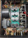
Today I decided to install the replacement main filter capacitors that I had assembled previously. I carefully marked and removed the old oval capacitors and replaced them with the assembled replacements. I was assuming it would be a simple swap of components but that was not to be. The terminals on the original oval caps and their replacements lined up against each other perfectly but unfortunately when they were all installed there were some descrepancies getting things to line up with the connecting strips on the F-2845 Power Supply circuit. After some manipulation and slight enlargement of the mounting holes on board #4 things fit together.

I double chenked everything and then plugged the AU-919 into the DBT with a 100W bulb and hit the power switch. The bulb burned brightly but not full brightness. I turned off the AU-919 and started investigating. I measured resistance from the negative rail Blue Wire terminal next to diode D03 to ground and was a dead short. I thought about this for a while and then I removed the assembled replacement caps to confirm I did not make any mistake assembling them. I then measured the resistance from the same terminal to ground and the short was gone. I looked at the bottom of the circuit board on the assembled replacements and wondered about the clearance between the oval cut-outs in the AU-919 chassis and the soldered terminals on the replacement caps. I measured everything and it looked like things were close but should be ok. The only way to really confirm the clearances would be to remove the F-2845 power supply board and visually inspect the clearances with the replacement caps mounted. I decided against this approach as removing the F-2845 board was an undertaking I did not wish to repeat.

I decided to mask off the connections on the underside of the replacement cap circuit boards with vinyl electricians tape. I then re-installed then and confirmed that the short that I detected previously was not present on the same lead or any of the others. I then pludded the AU-919 back into the DBT and powered it on. The bulb glowed and then dimmed as it should have previously. I then gradually brought the AU-919 up to full line voltage with a variac while watching the bias and DC offset voltages. Everything looked good so I connected up the speakers and played music pretty much all afternoon.

I think that the AU-919 sounds subtly better with the new caps, again, hard to quantify but better, bass lines a bit better defined and other subtle differences.

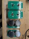
Here is a picture of the underside of the replacement cap boards. You can see the terminals that I referred to.

PXL_20260117_041714806 (1).jpg

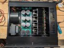
Here is a picture of the replacement cap boards installed in the AU-919. I think it is a pretty clean look but know many prefer the look of the original oval caps.

PXL_20260124_182444295.jpg


My final test will be to determine the clipping point with the replacement caps installed to see if it changed with the new caps. I also have to decide long-term how comfortable I am with the vinyl tape solution I employed to resolve the short circuit issue.
 
Last edited:
I can’t post a link due to rules restrictions but Google : Battery PVC Heat Shrink Tube Shrinkable Tubing Insulated Film Wrap Lithium Case Cable Sleeve.

Check the size you need and the heat shrink ratio to determine the right size .

Ones you have it and you test that it shrinks to the right amount , remove from the originals the label(lid) on the top ( you will need to cut off the original sheave) so you can use it as a lid again to the new capacitors assembly.

If you want to go further , paint the PCB black as the heat shrink will be black ; or order new PCB black…

Sorry my English vocabulary is limited, I hope you got the picture ….
 
Thanks for the information Sui-Yogi! My immediate plan is to leave the replacement main filter caps in place. At some future time I may re-stuff the original oval caps and re-install them but that is a future project.

I did repeat the clipping test with the replacement filter caps and the results were essentially the same, at 30V RMS the AU-919 started to clip which is the same result as I got with the original oval caps installed.

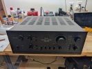
Here is a picture of the AU-919 completely re-assembled.

PXL_20260126_015626374-EDIT.jpg
 
Thanks for the information Sui-Yogi! My immediate plan is to leave the replacement main filter caps in place. At some future time I may re-stuff the original oval caps and re-install them but that is a future project.

I did repeat the clipping test with the replacement filter caps and the results were essentially the same, at 30V RMS the AU-919 started to clip which is the same result as I got with the original oval caps installed.

Here is a picture of the AU-919 completely re-assembled.

View attachment 3684893
In a nutshell for a properly designed and operating amp of this type, clipping will ultimately be determined by the power supply voltages either feeding the output transistors or the driver transistors or both. Clipping is running out of voltage swing.

Unless the original capacitors were REALLY REALLY bad, new ones should not have any effect on steady state output power.
New caps can certainly have an effect on dynamic current delivery though.

You have done a really nice job with the restore and documenting it here. Bravo :thumbsup:
 
Back
Top Bottom