• The move to the new server is done. There are some software and database maintenance updates in process. This has us passing the hat around to help out. We appreciate any donations. Seriously, even a dollar helps. The payment page may be found here - https://www.audiokarma.org/support.html

BIC Turntables

You are not kidding about less than critical about parts. Two of the 39kohm resistors on my board measured in the mid 20's.

Look at the color bands on the resistor and see if they're actually 39k or not.

Although, sometimes when you measure a resistor "in circuit", it will read LOWER than when you take it out.
 
What is what I'm getting off the leads to the motor.

I tried using an image linked from my web server but it would not work, nor can I remember those tags from this post.

Well, at least they are nice sinewaves. When the voltages are adjusted, as in the procedure, the voltage to the other coil is supposed to be within .3 volts and if not, BIC recommends changing the whole board but I'm sure it could be trouble shot down to component.

As far as phase, I am not a circuit design expert but would the bulb completely extinguish if the phases were 180 degrees from each other? In lieu of having an oscilloscope, I have always made the adjustment so the bulb is absolutely steadily and dimly lit. It is possible to get the bulb to burn brightly but that is incorrect and would indicate to me that the phases are 0 degrees apart. I can't remember the behavior of the motor/platter in that instance.

The adjustment can be made for anything in between, too, with the bulb pulsing at various rates which would indicate various phase differences and varying phases through time. I wonder if a fixed 90 degree difference is the correct setting. I can't remember if I was able to completely extinguish the bulb.

Doug
 
Look at the color bands on the resistor and see if they're actually 39k or not.

Although, sometimes when you measure a resistor "in circuit", it will read LOWER than when you take it out.

Yes, unless you can be sure there are no other components in parallel with the measured resistor, at least one lead of the resistor must be disconnected from the circuit for an accurate reading.

Doug
 
An electronics friend looked at the schematic is the sine should be 45*, which it is.

After making this post I went through the settings process again and have it spot on.

I do not like the Stanton 600ee that came on it. I will likely transfer my AT-95e to this and buy an AT-VM95ML for my other table.

Next up is designing and building a plinth.

My main hobby is woodworking.
My main gripe about these tables is their susceptible to skipping with the most minor vibration - as I recall. Also, the rubber bumpers are hardened.

I am considering a plinth that floats on repelling magnets. Not because it is a reasonable solution, because these are pandemic times and I have time to kill.
 
Note sure if this article has been linked here before.
I am including useful specs from the article.

If you are interested in reading, the review starts on page 58.
https://worldradiohistory.com/Archive-A ... 976-06.pdf

Key bits of info for future reference via google/forum search.

Wow and Flutter: Better than 0.05% w rms.
Rumble: Better than -65 dB DIN.
Tone Arm: Tubular aluminum. Length:
Pivot to stylus, 216.2 mm (8.51 in.)

From the article linked above:
Wow and flutter were measured separately, with the former measuring 0.04%-this resulting from measurement of frequencies below 6 Hz-and flutter-frequencies between 6 and 250 Hz-at 0.03%, and a total over the range from 0 -to -250 Hz measuring 0.05%. Range of speed control on Model 980 was measured by reproducing a 1000 -Hz record and feeding the output to a counter, with the range extending from 967 Hz to 1031 Hz, or just slightly over ±3%.

Model 960, with no means of varying speed, reproduced the 1000 -Hz tone at 1001 Hz.
Rumble, which is probably the most important figure in any report on a turntable, measured 48 dB below the standard level of 3.54 cm/sec at 1000 Hz. Converted to normally reported figures, this means a rumble figure of -66 dB, since rumble measured on a flat system is generally accepted as being 18 -to -20 dB lower than the acoustically perceived level. This is borne out by using the DIN test record No. 45544, "Rumpel-mess-schallplatte," and the specified measuring techniques, which produced a figure of -64 dB.

 
Of course, the "expert" turntable audiophiles will still poo-poo these tables. I think I read every review in the world about the BIC's back then, both before and after I bought my first 980.

Doug
 
I just ordered a new AT-VM95ML to go on my AT-LP120 and moved the AT95e to the BIC. It does sound quite good.

Still not sure if I am going to keep the table or give it to my brother, that may be dictated by just how much work I put into building a plinth. I'm a woodworker. I go overboard. Its what I do.
 
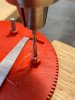
I bought a 960 as a parts donor and discovered two pegs broken off the Cam disk. I've already spent far to much dinking around with these so I set about repairing it. I knew I need two pegs that are .148" in diameter.

Set about searching the shop for something suitable and discovered these nails are .147" diameter; close enough for me.
0.jpg

The closes thread size to .147" is #6-32
Fortunately I had the taps and dies to do this.
Drilled out the plate.
1.jpg

Tapped the hole
2.jpg

Threaded the nail and cut to length:
3.jpg

After a test run I applied superglue to the threads to lock in place.
I am aware it is in the cam track but I made sure it is absolutely flush to the surface. No indication of issues as a result.
Pegs.jpg Pegs2.jpg

It works flawlessly and, aside from a little metal on metal noise from the levers when actuated, you'd never know I modified it.

Now I have a 960 to give to my brother.
 
There should only be two pegs or pins.

BIC originally manufactured them with three but the third one (closest to the trip lever and the one that ended up going through the cam track) was causing the cam to not end up in the detent position and so they stopped including that third one and removed it on the existing cams.

This is the subject of one of the service bulletins available at the Vinyl Engine library.

Now, it may be that you can leave it there but I would check to make sure the blanked out area around the outside gear track ends up centered at the spindle after a cycle so it can't snag the teeth on the spindle and start a false cycle.

Doug
 
The two pegs or pins would depend on the production year, I believe. In this case there were obviously two broken pins so I replaced them both. The only one I had on hand for comparison is my other BIC, and that too has three pins.

Both tables have been cycled dozens of times and I've yet to have either mess up on alignment.

More importantly, I am pleased I could fix it for roughly 6 cents in materials and maybe 45 minutes of my time.
 
If there were any cams in stock/production when the change was made, BIC broke the third one off. The problem wasn't consistent, however, and many tables probably worked fine with all three pins there.

Doug
 
If there were any cams in stock/production when the change was made, BIC broke the third one off. The problem wasn't consistent, however, and many tables probably worked fine with all three pins there.

Doug
Its good to know. If I restore any more, I'll only need one nail instead of two.

I honestly wondered if I should put in two as the NOS ones only have two; I opted to replace what was missing to cover my bases.
 
In 1982 my dad brought home a BIC 980 to replace his aged Garrard Model 50 changer.

He asked me to get him a cartridge for it and set it up. I paid $40 for a brand new Pickering XV15 1200E. It was a pleasure to set up. It was a VERY impressive table.

My brother in California has that table now. Still works well. He cleaned and lubed it 6 years ago. He’s not interested in replacing it.
 
I bought a 980 for myself.
I bought a 960 as a parts donor, realized I could still make it a viable table too. Gifting that to my brother.
Dad learns about my hobby, he wants a 980; I found one locally.

Apparently I am becoming quite proficient with these tables.

I've hit a setback.
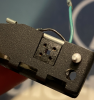
The wires in the headshell for my brother are ruined. The metal tabs on the connector mating with the tonearm broke off.
I can make my own connector block but need to find female connectors of the correct size.

Trusty calipers tell me the pins off the tonearm are .85mm.
For the life of me I cannot find female soldered connector of that size.

This is the block I can create from scratch.
I am looking for the female connectors I can use on my DIY version.
Screen Shot 2020-12-14 at 11.38.36 PM.png

This is the backside.
Screen Shot 2020-12-14 at 11.41.11 PM.png
 
Yeah, that's a bummer. Those connectors were probably proprietary but I don't know for sure. I have three shells missing the whole connector assembly I got in an auction. I had one assembly with one connector with a broken tab but because both grounds go to the same place in my Heathkit amps, I just soldered both wires to one ground tab and it's fine.

That being said, I still think the BIC design is superior to the standard threaded collar type headshell used on most turntables. Much less mass and gold plated pins/sockets. I have never had one problem, over 44 years, with contact between a headshell and the tonearm. They just always work. And the variable angle adjustment is so much better than trying to vary the VTA angle at the rear of the tonearm. I always snicker when I read posts about making sure the arm tube is parallel to the record surface.

Doug
 

From what I've read the correct stylus position is dead center of headshell (left to right) and dead center of the M/A mode switch (fore and aft).

I made made a block of wood to use as a buck to assemble the parts.
Then ran through table saw to give clearance for the mode switch and lever finger.
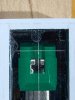
Finally, cut the clean lense, marked coordinates base on information above and inserted on the bottom.

I had already set the stylus on one headshell using a simple protractor, and quite certain that was exact. When I placed the headshell in this gizmo if lined up perfectly; this gives me great confidence in its accuracy.

The next one I make will not have the stylus tip fall on the crosshairs, instead I will space the lines 0.1mm all around the center point of the stylus point with a will offer a window 0.4mm sq to eyeball the position.

This works with the solid plastic and the skeletal headshells.

I need to make at least three - one for each table I'm giving away and one to keep.
 
Made a few more revisions until I landed on this version.

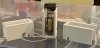
I made three, one for each turntable.

Obvious function, setting stylus.
I added two lines either side to assist in aligning cart body.

ACAA1EB6-890D-4716-964A-995FDCEA0AB6.jpeg

2A7238E8-B286-41FE-9FA8-DCFC3AAC0D2F.jpeg

Can be used to adjust head shell/tracking angle.

21BB513E-78C9-425E-AD08-07D37BFBD2F4.jpeg

Is this close to the original setting gauge?
 
Yes. I used to have two of the originals but gave one to my daughter and she later gave the 980 I gave her to my son but I don't think she knows where the gauge is.

Anyway, I guess I have always thought the original gauge placed the stylus tip at the rear edge of the M/A/ slide but sometimes a little bit off. I don't think it's that critical. Whenever I compared setting the stylus position with the gauge compared with a protractor, it always matched.

I'll get my original gauge out tomorrow and check it again.

Doug
 
I'll get my original gauge out tomorrow and check it again.

Doug

Please take photos.

I may make a half dozen and put on ebay or elsewhere to see if there in interest.
It is truly a brilliant little piece of kit.
- leaves zero doubt as to stylus alignment.
- leave zero doubt as to tracking angle.

In retrospect, it is VERY UPSETTING to think more manufacturers do not provide similar setup jigs.
They know where the tonearm pivot is in relation to the spindle.
They know within a few hundredths of a mm where the stylus should be on their headshell/tonearm combination.
They should provide similar tools for alignment.

I just pulled two of these headshells and two carts and aligned them at the dining room table using the tool I made and a magnifying glass.
I now have ABSOLUTE 100% confidence these are correct.
No printing protractors and checking their measurements.
No iterative process between point A and point B.
No leaning over a turntable and squinting.
Simple jig, flat surface, well lit area, two screws and an adjustment; DONE.

* I know my crosshair is +/- 0.0015" of exact point in space. I think this is close enough.
 
Back
Top Bottom