• Please note that Audiokarma will be offline briefly for updates early on Monday morning, September 28th.

Birthday Present! Denon DP-1200

Last night a friend came over and we did some more testing. While being grounded to the chassis, we got inconclusive/abnormal readings at the power prongs and magnetic head prongs on the power pcb. Also, the two main resistors on the pcb got scorching hot to the touch while we had it on, so we turned it off and I figure I need to go component by component on the power pcb.

Thoughts?
 
Last night a friend came over and we did some more testing. While being grounded to the chassis, we got inconclusive/abnormal readings at the power prongs and magnetic head prongs on the power pcb. Also, the two main resistors on the pcb got scorching hot to the touch while we had it on, so we turned it off and I figure I need to go component by component on the power pcb.

Thoughts?
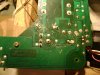
Well-focused pic of the underside of the motor PCB, and if possible post the schematic.
 
Last edited:
updated pic of the PCB.

See if you can get the service manual from this link.

https://dl.dropboxusercontent.com/u/694782/Denon DP1200/ve_denon_dp-1200_service.pdf

Take a hard look at the solder connections on the upper 2/3 right portion of the board, that's the primary motor drive ckt. The left side-to-top is the servo-control amplifier/integrator from the tape head tach. If this doesn't do it there may be a problem with the black block cap(s) one of which is a phase shifter needed for the motor to run at all. It'll get warm and draw current without turning if this C20 cap is bad.
If R19 & R23 are getting hot I'd suspect that 16 volt zener diode D4 is shorted and needs replacement, the neon strobe lamp is part of the series current limiting ckt for the DC PS and must light for the thing to be workable. If it lights extremely bright the DC supply zener D4 may indeed be shorted, all voltages sourced from the DC PS will be very low of non-existent if so. FYI the ground plane of this TT is not part of the power supply circuit and all parts of the PS ckt WILL be electrically 'hot' to potential external ground/return points, EXERCISE EXTREME CAUTION!! as there is no internal isolation/power transformer!! This is why there is a signal isolation transformer for the tach sensing head BTW, stay off & away from this ckt when voltage testing to avoid frying the head and/or xformer. All DC voltage checking MUST be done from PS low-side/return, again be VERY careful!
 
Last edited:
Unfortunately with my little Craftsman 82141 Multimeter I dont believe I have a way to test the caps.

I did go around and check continuity and the resistor values. All seems well there.

It does seem as though there is some funky stuff going on towards the output of the power PCB.

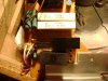
Here are closer pics.
 

Attachments

  • DSC00850.jpg
    DSC00850.jpg
    91.4 KB · Views: 93
  • DSC00853.jpg
    DSC00853.jpg
    78.8 KB · Views: 64
Unfortunately with my little Craftsman 82141 Multimeter I dont believe I have a way to test the caps.

I did go around and check continuity and the resistor values. All seems well there.

It does seem as though there is some funky stuff going on towards the output of the power PCB.

Here are closer pics.
I think I see one solder connection that looks different from the others that may need a reflow, it's the bigger pad at the right end of the upper 'U'-shaped trace and the motor will not run if it is open. I'm not sure of your skill level so I'll try to keep it simple and keep you from getting in over your head. After this we need to check diode D4 with the diode checker on your DMM, it should check 'open' in one direction and appx 0.75 the other way.
 
Last edited:
i'm capable of of soldering on pcb's ok. i'll try to get to it tonight. i'll check the diode as well and report back.
 
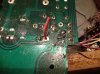
I think I see one solder connection that looks different from the others that may need a reflow, it's the bigger pad at the right end of the upper 'U'-shaped trace and the motor will not run if it is open.

Are you talking about the one I have a wire going thru in the attached pic? If so, there is nothing on the other side of the board related to this position. I can fill it if need be.
 

Attachments

  • image.jpg
    image.jpg
    106.3 KB · Views: 50
After this we need to check diode D4 with the diode checker on your DMM, it should check 'open' in one direction and appx 0.75 the other way.

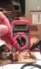
Attached are the results of the diode test. Sure seems funky.

BTW, getting these pics was the most difficult thing I've done all day, even after sanding down my speakers. You ever tried tapping the screen of your phone with your nose while taking a reading on a diode?!? HAHAHA
 

Attachments

  • 2013-04-29 22.11.43.jpg
    2013-04-29 22.11.43.jpg
    58.1 KB · Views: 70
  • 2013-04-29 22.12.31.jpg
    2013-04-29 22.12.31.jpg
    57.5 KB · Views: 72
Attached are the results of the diode test. Sure seems funky.

BTW, getting these pics was the most difficult thing I've done all day, even after sanding down my speakers. You ever tried tapping the screen of your phone with your nose while taking a reading on a diode?!? HAHAHA

That doesn't seem right, check D5 and let's compare that.
 
D5 is a different kind of diode, so I also checked d1 and d2. They both give me 664 and 665.

Diode checkers measure voltage drop, yours in millivolts/thousandths of a volt. These diodes can be paralled by large-ish capacitors so the test should be done for a few seconds each direction until stable.
D4 is a zener diode, used here as a simple shunt regulator. Zeners can behave as 'normal' diodes as one-way electron gates but have a predictable reverse "breakdown" voltage threshold that makes them useful for voltage regulation when the maximum current flow is limited below their wattage rating. They almost always check forward conduction breakdown at ca 750mV and reverse breakdown is what-ever they are rated for as regulator 'standards' and usually tests 'open' circuit in this type of testing. Standard Silicon diodes have a high-to-"infinite" reverse breakdown voltage and forward breakdown of ca 600-675mV. Therefore, D5 checks normal and as D1 and D2 are in reverse-parallel the reading you get is normal and both are good.
D4 is not right, zeners more than other diodes can prove "mortal" over time and replacement is required when they go 'wonky'. We may need to do that here to go forward, use the same voltage rating and the same or preferable the next larger wattage rating that fits when in shunt service, installed with the same indicated polarity.
 
Last edited:
You need a 5.8, 6, or 6.2 volt 1or 1.2 W axial zener diode. The other diodes are conventional unidirectional diodes and are fine as-is.
 
Well I went to Frys and the dude looked up the Denon part number. It came back with 1/2 watt. Is that going to be a problem?
 
Back
Top Bottom