fizzgig
Well-Known Member
C20, in series with one of the motor coils, it's the phase shifter that makes the thing turn.
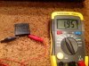
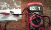
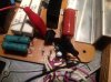
C20 was within tolerance. See attached pic.


C20, in series with one of the motor coils, it's the phase shifter that makes the thing turn.

OK then, this makes me suspicious of diode bridge D3. If one of the diodes is bad it could put DC onto the motor and draw excessive current without turning the motor or just act as a partial short-circuit, a 1A/400V bridge should be an adequate replacement if it is defective.
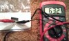
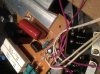
I pulled the diode bridge and tested. Attached are the results. Should I still replace it?
Yes, cheap enuff to eliminate the possibility of failure under stress.

I keep coming back to this thread praying to hear that the motor has turned. Such a long-running drama, could be a mini-series already! I sure am curious what is heating up those resistors as I can tell you there was no such thing going on with mine back when I had it.Found that NTE167 (200V 2A) is a proper replacement for 1S2372A. So did a phone order and stopped by Mouser to pick it up.
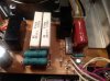
Installed. Resistors R20/24 still get burning hot and no motion from the motor.
I keep coming back to this thread praying to hear that the motor has turned. Such a long-running drama, could be a mini-series already! I sure am curious what is heating up those resistors as I can tell you there was no such thing going on with mine back when I had it.
I for one am looking forward to that day! I enjoyed mine while I had it, just too may tables and too much curiosity....Yes, I have faith that PIO can help me resurrect this beauty. :thmbsp:
http://m.youtube.com/#/watch?v=VcjzHMhBtf0&desktop_uri=/watch?v=VcjzHMhBtf0
There is a yellow wire going from the main board to the arm control board, lift this wire, power up and see if the resistors still get hot.
If so try to isolate pin 15 on the controller IC TC955 and check again for resistor heating.
I use solder wick to "dry" them out until the leg freely moves, then ensure it is not touching the edge of the eyelet.fizzgig said:Quote:
Originally Posted by Pio1980
There is a yellow wire going from the main board to the arm control board, lift this wire, power up and see if the resistors still get hot.
PIO, to confirm, you are stating to remove W-13 from the power PCB and then engage power and check the resistors for heat.
Quote:
Originally Posted by Pio1980
If so try to isolate pin 15 on the controller IC TC955 and check again for resistor heating.
In this step, what would be the best way to isolate the individual pin? de-solder the whole thing and make jumpers for the rest of the pins? Or, de-solder and put some rubber around it? lol. Not sure of best practice here.
There is a yellow wire going from the main board to the arm control board, lift this wire, power up and see if the resistors still get hot. If so try to isolate pin 15 on the controller IC TC955 and check again for resistor heating. This IC was used in other TTs and is not an exclusive rarity.
The motor ckt can be checked with a temporary quick-check direct connection, carefully bypassing D3 and controller ckt (jumper other diode leg points on board NOT marked + or - on the diode), and powering up momentarily with platter off. Getting the jumper wrong will cause havoc, take care!
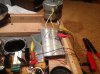
PIO please verify from the pic that I have placed my jumpers correctly on diode D3. They are connected to "~" pins, not + or -.
These jumpers then connect to the motor via the yellow and black wires, correct?