• The move to the new server is done. There are some software and database maintenance updates in process. This has us passing the hat around to help out. We appreciate any donations. Seriously, even a dollar helps. The payment page may be found here - https://www.audiokarma.org/support.html

Brainstorming a push-pull 6L6GC stereo amp

Well... This is where I feel really stupid. Or something. I figured -- hey, I'm waiting for the snubber caps, so I'll wrap up some of the other little random tasks ... reconnect all the stuff I had previously disconnected (fan supply, input jacks, etc.) and since I decided to switch from 6N2P to garden-variety 12AX7 (which I'd been using with an adapter temporarily), I'd reconfigure the heater circuit on the first stage and ditch the adapter.

After reconfiguring the heater circuit on the 9-pin socket, the noise was essentially gone. The previous solder joints were good, the twists tight right up to the socket. I'm a little perplexed, but I'm not complaining.

Note that the spikes are still visible on the scope trace. I guess those are coming through as some of the not-terribly-bad white noise / hiss that is still present (that I expected to tame with the feedback loop, which is still not connected).

I still plan to put the snubber across the PT secondary when the caps arrive. But in the mean time, I'm going to tackle the feedback loop.
 
Your positive finding with the 10M shunt resistor at 6SN7 G2 is most peculiar. It forces a degree of DC imbalance in the diff amp, of course. I wonder if this is one of those weird cases where the accidentally induced imbalance, against all odds, just happens to null unbalanced power supply noise pickup via radiation (EMI).

It should be okay to try the 1nF film caps you have, just long enough to see if a snubber will be effective.
 
Well, I figured out what was wrong with my feedback loop, too... I made a simple wiring mistake that resulted in feeding back to the opposite channel. Swapping the location of two wires fixed my problem right up, and it sounds very good with a 6.8K feedback resistor good for -11.4dB of feedback according to the math.
 
Here's a couple of random performance figures:
  • Estimated input sensivity was 415mVrms, measured 439mVrms.
  • Power just shy of clipping @ 1KHz: 28.5W
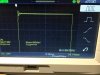
  • 1KHz square waves @ 1W look pretty respectable. See photo 1. Photo 2 is the same, zoomed in a bit to get a better look at the overshoot. A 330pF cap across the 6.8K feedback resistor tamps it down fairly well (photo 3).
  • Using 1KHz @ 1W as a reference, frequency response is essentially flat from 25Hz - 15KHz, and is 1dB down at 20KHz (it comes right back up if I remove the feedback cap).
  • Noise with shorted inputs is around 3mVrms on the 8 ohm tap.
Another random tidbit... Of all the 6SN7s I had, the best pair of matched triodes were some NOS Russian 6H8C (6N8S in Latin script) with 1958 date codes. They look pretty boss in front of the 6П3С-Еs, with their "OTK" stamps and taller-than-US-made-6SN7 bottles.
 

Attachments

  • IMG_3551.JPG
    IMG_3551.JPG
    82.6 KB · Views: 35
  • IMG_3552.JPG
    IMG_3552.JPG
    83.8 KB · Views: 35
  • IMG_3553.JPG
    IMG_3553.JPG
    92.2 KB · Views: 36
Last edited:
Ok, WRAP UP!

I spent some time putting it through its paces while I cleaned up the bench and helped my son clean some old vintage O-gauge model train track. No hiccups, and sounded pretty good in the admittedly crappy garage environment.

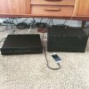
Since this amp is destined to be the power amp in the main (living room) stereo system when we move back into our remodeled house in a couple of months, I decided to drag it upstairs and temporarily connect it to it's pre-amp (a Parasound 2100) and the speakers that it'll be used with (Sansui SP-X9s). (See photo. Ignore the mess of cables under the furniture; temporary living arrangements are not often dialed-in for total neatness.)

After connecting everything up, I did a noise check. The SP-X9s are rated at 101dB @ 1W/1m, so they're going to make noise obvious. At distances most humans consider normal, there is none perceptible (hum, hiss, pops, nothing). It is possible to hear some very slight raspy hum if you get your ears right up to the speaker grilles. I am not concerned with this because it is otherwise inaudible.

I've listened to a variety of music through it over the last hour or so... some tween-pop (to make my kid happy), some Beatles, some Phoenix, and have cued up some Les Paul. With the tone controls on the pre-amp bypassed, it so far all sounds fantastic. Considering I'm down 1dB at 20KHz, it's nice to know that I have some headroom in the tone controls if I want to boost high frequencies sometime down the road. Input sensitivity of the power amp seems well matched to the pre-amp; I have not backed off the input attenuator at all. Increasing the first stage grid stoppers was also a good idea -- I have successfully held my cell phone right next to the power amp and not picked up any RF chatter.

The remote power-on circuit (driven by the pre-amp) works perfectly. This furthers the goal of "fewer switches to fiddle with" that I often hear complaints about from my family.

Overall, I'm really happy with how it turned out, and am really glad I abandoned the goofy power supply I had originally spec'd out. It sounds great, it looks really cool, and I get to say "Hey, I built that!" in case anyone asks :)

So, a huge THANK YOU!!!! to all the folks who helped out with this project, answering my silly questions, sharing experience, and helping with debugging.
 

Attachments

  • IMG_3558.jpg
    IMG_3558.jpg
    106.1 KB · Views: 36
Last edited:
If you get a chance, put it back on the bench and run an 8KHz to 10KHz square wave through it with a dummy resistive load at 1 watt, and show us the scope readout of that. That will give you a much better idea of what that initial overshoot and damped ring looks like. You might be able to fine tune the response a bit more. My eyebrow is raised just a hair that response is down 1dB at 20 KHz. I'm thinking it should be possible to make it flat as a pancake till about 30 KHz and 1dB down at ~38 KHz. At least that's what I was able to obtain with Hammond 1650H's. I recall you are using 1650HA's?

How big is your feedback cap?
 
If you get a chance, put it back on the bench and run an 8KHz to 10KHz square wave through it with a dummy resistive load at 1 watt, and show us the scope readout of that. That will give you a much better idea of what that initial overshoot and damped ring looks like. You might be able to fine tune the response a bit more. My eyebrow is raised just a hair that response is down 1dB at 20 KHz. I'm thinking it should be possible to make it flat as a pancake till about 30 KHz and 1dB down at ~38 KHz. At least that's what I was able to obtain with Hammond 1650H's. I recall you are using 1650HA's?

How big is your feedback cap?

Yes, 1650HA. I can get it back on the bench for those tests perhaps tonight, but certainly sometime this week. Feedback cap is 330pF (it's the smallest I had on hand... I plan to order a smattering of smaller values), bypassing a 6.8K resistor. The total feedback is -11.4dB.
 
If you get a chance, put it back on the bench and run an 8KHz to 10KHz square wave through it with a dummy resistive load at 1 watt, and show us the scope readout of that. That will give you a much better idea of what that initial overshoot and damped ring looks like.

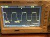
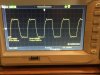
Ok, here are traces of 8KHz and 10KHz square waves.
 

Attachments

  • IMG_3559.JPG
    IMG_3559.JPG
    102.1 KB · Views: 37
  • IMG_3560.JPG
    IMG_3560.JPG
    101.8 KB · Views: 36
It's not perfect, but that's definitely far from "out of control", too. It's probably better than a lot of stock production amps built in the old days!

Regards,
Gordon.
 
That last little bit on the up swing where the slope changes as it approaches the first overshoot I think is where you are loosing your bandwidth. Usually slope changes like that are caused by too aggressive of a band limiter on a low pass filter. Additionally it does seem like there is enough feedback there in the circuit to support a little better bandwidth. Looking at your last posted schematic it doesn't look like you have any HF contouring filters installed, so the only thing I can think of that's causing this is the transformer itself. You might try one of a) increasing feedback a little (maybe 14 dB or so), or b) reducing the feedback cap to 220 pF and adding some HF contouring (a low pass step filter, maybe starting with 10K + 100 pF). Put the 10K resistor on a pot initially and dial it in to see if you can get that initial rise to have nearly constant slope all the way up to the peak of the first overshoot.

For reference and for what it's worth (since transformers are different), here is a scope shot of an 8KHz wave being reproduced through my amp with Hammond 1650H's. Our amps are similar in that they both utilize the same frontend topology, but mine uses a 6DJ8 gain stage (with 10.5 dB global feedback) instead of a 12AX7. To get that response, I needed three tuning elements: feedback cap, step network, and band limiting cap installed from the brown leg of the OPT primary back to the cathode feedback junction point.
8KHz_with_plate_cap.jpg

I know that the 1650H and 1650HA use totally different interleaving methods so the HF characteristics I expect will be different. In other words, it may be the best you can get. Anyway I just offer this as ideas to try to squeak that last little bit of performance out. I think you've done a really great job on your amp.
 
b) reducing the feedback cap to 220 pF and adding some HF contouring (a low pass step filter, maybe starting with 10K + 100 pF).

I assume this would be cap + resistor in series, cap connected to the output of the 12AX7, and resistor to ground? (Sorry, I'm in new-to-me territory with this HF contouring stuff...)
 
Yup. Ultimately it doesn't matter though. But for debugging/tuning, I like to do it with the cap installed on the plate because the cap blocks the DC, and if you're trimming a pot by hand, you don't want to slip with your fingers and touch one the high voltage points (I've done it--learned the hard way. Luckily it was only ~100V DC so I survived). But when you install the final circuit it doesn't matter which order.
 
Last night an old friend of mine and fellow ampaholic was in town, and since it was too late to play guitar at levels appropriate for such an occasion[*], we decided to fiddle with this 8KHz square wave problem a little bit instead.

We didn't do much more than increase the feedback (from -11.4dB to -14.2dB by clipping a 13K resistor in parallel to the 6.8K feedback resistor). This didn't do anything more than reduce the gain -- the 8KHz square wave response seemed otherwise unaffected...

[*] We made up for the lack-of-shred last night with some absurdly loud playing before lunch today. He brought along one of his own creations, a monstrous 70W PP EL34 high-gain head that affirmed my decision to always build L-pad power soaks into my guitar speaker cabinets. Geezus that thing was ridiculous.
 
Finally got around to doing some THD measurements. (Actually, great excuse to play with a newly acquired toy -- Keithley 2015.)

Set to measure up to the 9th harmonic:

At 1W output:
1KHz - 0.1%
10KHz - 0.2%
20KHz - 0.3%

At 9.3W output:
1KHz - 1%
10KHz - 0.7%
20KHz - 0.8%
 
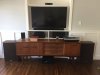
At long last (holy cow, I never want to remodel a house ever again), the space that was built specifically for this amp is finished. Thanks again, all you awesome AK'ers, for all of the help and advice during the design / build / debug process!
 

Attachments

  • IMG_4471.JPG
    IMG_4471.JPG
    49.9 KB · Views: 31
Back
Top Bottom