
• The move to the new server is done. There are some software and database maintenance updates in process. This has us passing the hat around to help out. We appreciate any donations. Seriously, even a dollar helps. The payment page may be found here - https://www.audiokarma.org/support.html

Brainstorming a push-pull 6L6GC stereo amp

However, in this particular case, you might succeed by adding resistance anywhere in series with the cap that AC-grounds G2.

Well, the quick test of jumpering in a 10K or a 150K resistor between G2 and the cap didn't have an effect. To do it correctly, I need to put in a couple of terminal strips (one for each 6SN7 socket). But that's going to have to wait until a bit later. If you have any other suggestions, however, I am all ears.

Thanks!
 
I admire your persistence with this. It makes me wonder about the feasibility of simulation programmes, which could make the adding and removing of components so much quicker and easier. This is just a thought--I don't want to divert this thread away from getting your project done.
 
Last edited:
It also occurred to me that perhaps I'm not using a large enough grid stopper on the first stage.

So, thought about this a little more while I had my coffee this morning. I realized that I was being lazy when I selected the grid stopper value for the first stage... Lazy as in "1K is what I used for the last 12AX7-type input stage I built, that'll probably be fine". That was in my SE 6L6 amp. I light-bulb-moment remembered that I picked that small value for the following reasons:
  • The intended usage of that amp was to have a signal source (iPod, whatever) connected directly, so the volume pot would, most of the time, be providing a signifiant amount of input resistance by virtue of it not being cranked all the way up.
  • The open loop gain of that first stage was high (73), meaning the Miller capacitance was up in the 180pF range.
In other words, high frequency roll-off was a concern.

But in this case, there are a couple of key differences:
  • This amp has an input volume pot, but it will be connected to a pre-amp that has the volume control. The input pot is meant only to fine-tune the input level, and will NOT be providing any significant input resistance.
  • The open loop gain of the first stage is much lower (33), so the Miller capacitance is only about 84pF.
Because of this, I don't really have much to worry about in terms of high frequency roll-off, so I can easily get away with a much larger grid stopper on the first stage, say 33K or even 47K. (I also realized I mis-labelled the input pot on the schematic -- it's actually a 100K pot, not a 50K pot.)
 
Ok. Tried a couple of things tonight. First, bumped the grid stoppers on the 12AX7 to 33K. Second, squeezed in another tag strip and added a 47K series resistor between the second 6SN7 grid and the .22uF cap to ground, with the 47K resistor having a minimized lead length on each end. I was not able to detect any difference, and the scope probe on that pin still snuffs out the noise.
 
Well, if it looks like a duck, and it quacks like a duck... Maybe it's worth trying a little shunt capacitance to stand in for probe tip capacitance. Something around 15pF, perhaps? If it works and doesn't impair anything else, then I say it's a legitimate fix.
 
Well, if it looks like a duck, and it quacks like a duck... Maybe it's worth trying a little shunt capacitance to stand in for probe tip capacitance. Something around 15pF, perhaps? If it works and doesn't impair anything else, then I say it's a legitimate fix.

I'll give it a whirl, though the smallest caps I have at the moment are 330pF.
 
You can make small caps by twisting insulated wires together, but it's hard to know actual capacitance unless you have an LCR bridge or a good C meter.
 
Well, if it looks like a duck, and it quacks like a duck... Maybe it's worth trying a little shunt capacitance to stand in for probe tip capacitance. Something around 15pF, perhaps? If it works and doesn't impair anything else, then I say it's a legitimate fix.

Ok, I ran the experiment tonight with what I had on hand. Attached is the schematic as the amp currently sits, with the following exceptions:
  • NFB loop is not connected
  • 12AX7 inputs are grounded at the sockets (via alligator wires)
Looking at the right half of the 6SN7 you can see the 47K series resistor I added before the .22uF cap. I didn't pick that value for any reason other than "seems like a plausible grid stopper value".

With the 330pF cap I had on hand and a couple of alligator wires, I first tried bypassing just the .22uF cap. No change.

Next, I bypassed both the 47K resistor and the .22uF cap. This made the noise slightly worse. Not much, but discernible.

Next, I bypass just the 47K resistor. This had the same effect as the previous step.

I feel almost like that tells me the noise is entering through the ground circuit?

(Edit: Now with schematic. Oops.)
 

Attachments

Last edited:
The noise is, however, present on the grids of the R channel's output tubes, so that tells me it's coming from that channel's 6SN7..

(going back a few posts)...so is this 60 Hz or 120 Hz noise? Have you considered that on this channel it might be coming from the bias supply? Just asking...as it seems everything else that is obvious has been discussed/tried already.

Also, on one amp I built, I had same this situation (one channel noiser than the other). Turned out the noise was being injected into that channel from the power supply--not through the wiring directly, but from the layout/proximity of the power and filament transformers. I fixed it by putting in a heavily shielded wire from the output of the first gain stage to the input of the phase inverter, and grounded the shield at one end.
 
If your scope/probe can handle the voltage, try probing 6SN7 and 6L6 anodes to discover noise characteristics. Also, I wonder if probe DC loading has something to do with this problem. Can you kill the noise by shunting G2 to ground with a 10M resistor instead of the probe?
 
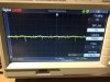
@kward: Well, let's see... 120Hz would be around 8ms period... Looking at a trace I took while poking around at this last Friday (see attached), it sure looks 120Hz-ish, but slightly inconclusive (5ms/div... 3 divs between the larger spikes [for 60Hz], but with a smaller spike smack in the middle of them [120Hz-ish]).

My bias supply is half-wave, but the little bias transformer is located below the chassis. It is at one end, and the noisier channel is located roughly centerline (about 8 inches away), (much) less noisy channel located at the opposite end (about 16 inches away). The transformer is this Triad model: http://catalog.triadmagnetics.com/i...ount-quick-pack-power-transformers-1/f4-120-1

@BinaryMike: I'll perform the 10M resistor experiment tonight. I do happen to have some of those :-) As for probing the 6SN7 and 6L6 anodes... I've probed the 6SN7 anodes using the 10X setting on my scope/probe. Power rail side of the load resistor, the trace looks pretty clean (those spikes aren't present); tube side of the load resistor is where I see the noise. I haven't probed the 6L6 anodes because the noise was being transmitted to the grids of the 6L6s, and the noise goes away if I pull the 6SN7s out of the amp. I could certainly do that, but because it's present on the grids, I would certainly expect it to be present on the plates.
 

Attachments

  • IMG_3522.jpg
    IMG_3522.jpg
    92.7 KB · Views: 6
The noise spikes are probably powerline related, judging by ~17mS spacing. You could prove it by triggering on the powerline.
 
On the amp I was previously describing, I was able to pin point the filament transformer as significantly contributing to the noise problem by unbolting it from the chassis, then physically picking it up and moving it around while the amp was on, moving it up and to the sides away from the frontend tubes by maybe three or four additional inches. It became very apparent at that point that proximity to the frontend tubes in that channel was the problem.
 
The noise spikes are probably powerline related, judging by ~17mS spacing. You could prove it by triggering on the powerline.

So, what would be a cure for that? Because they're spikes and not ripples, it doesn't seem like insufficient PS filtering... I don't have any noise suppression caps on my mains line (but then again I've never had this problem before)... I suppose I could try adding those (I have a stash of 300Vac .0047uF X1Y2 caps).
 
On the amp I was previously describing, I was able to pin point the filament transformer as significantly contributing to the noise problem by unbolting it from the chassis, then physically picking it up and moving it around while the amp was on, moving it up and to the sides away from the frontend tubes by maybe three or four additional inches. It became very apparent at that point that proximity to the frontend tubes in that channel was the problem.

Yah, I could unbolt the bias PT and move it around a little. I would be REALLY surprised if it was the main power transformer, being as it's a toroidal and they're supposed to be LESS noisy.
 
Those spikes could be caused by rectifier reverse recovery events, which excite power transformer winding resonance. Try adding RC networks of 1K and 1nF in series across the secondaries. Make sure the caps are rated to handle the abuse.
 
Those spikes could be caused by rectifier reverse recovery events, which excite power transformer winding resonance. Try adding RC networks of 1K and 1nF in series across the secondaries. Make sure the caps are rated to handle the abuse.

Oh, a snubber like you did in the Bonseki PSU? I have some 1nF 600V film caps, I'm assuming that will be fine?
 
Correct. 600V caps should be okay on a 320V winding. They should be metalized film, not film/foil.

Aw, rats. Makes sense -- you want the self-healing property of metalized film. The ones I have are 716Ps, which are film + foil. I'll order a handful of yellow tubulars.
 
If your scope/probe can handle the voltage, try probing 6SN7 and 6L6 anodes to discover noise characteristics. Also, I wonder if probe DC loading has something to do with this problem. Can you kill the noise by shunting G2 to ground with a 10M resistor instead of the probe?

Finally got a chance to try the 10M resistor experiment. Yes, while both listening and with the scope watching the grid of one 6L6, grounding G2 with a 10M resistor kills the noise in the same way as poking it with my DMM or with the scope probe.
 
Back
Top Bottom