• The move to the new server is done. There are some software and database maintenance updates in process. This has us passing the hat around to help out. We appreciate any donations. Seriously, even a dollar helps. The payment page may be found here - https://www.audiokarma.org/support.html

Brainstorming a push-pull 6L6GC stereo amp

Theoretically it looks like it will work. However I tried something similar to this and I couldn't get a 12V fan to rotate at ~8V pseudo DC. It would turn if I kick started it by hand, but it wouldn't start up on its own. I either needed more pseudo DC voltage or less ripple. I ended up using a three terminal regulator, and then the fan worked at any voltage I fed to it, down to about 4.5V. I thought about using a 12V AC or 120V AC fan, but couldn't find one that was quiet enough to use.

This is the quietest 12V fan I've been able to find: http://www.evercool.com.tw/categories/global/fan/evergreenfan/egf-8/egf_8.php
This one is extremely quiet at 12V and as quiet as an owl floating through the air at 8V, and still gives a reasonable air flow:

Of course my research was a couple of years ago, so there may be quieter ones today that put out that same cubic feet per minute rating.
 
This is the fan I ended up buying: https://www.amazon.com/gp/product/B0026ZPFDE/ref=oh_aui_detailpage_o03_s00?ie=UTF8&psc=1

19dbA at 2000RPM ... not as quiet as that Evercool, but moves quite a bit of air. I tried spinning it up with a 12V wall wart plugged into my variac, dialed back to give 6V out of the wall wart and that was fine ... I could put it on an LM317 if I need to and run it a tad lower than 6V if necessary. I'll experiment a bit before I making any permanent holes :) Simulation tells me I'll have 6.25VDC +/- .25VDC [edit -- originally mis-placed the decimal point] ripple with the above circuit. It tightens up quite a bit if I parallel 2 of the 4700uF caps.
Screen Shot 2016-07-02 at 10.55.48 AM.png
 
It might work. In my case the power supply worked with with one fan that was louder, but not with the Evercool. I can't remember how much filter capacitance I had on it.
 
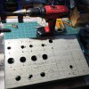
My least favorite part of the process is also the most satisfying when you see it come together.

(Metalwork was never my forte.)
 

Attachments

  • IMG_3444.jpg
    IMG_3444.jpg
    77.8 KB · Views: 45
  • IMG_3455.jpg
    IMG_3455.jpg
    70.8 KB · Views: 48
Well, I'm almost certainly going to be using a different transformer for this. I picked up a 400VA 320V toroidal and the experiments I ran last night have me pretty much convinced. It's not as pretty, of course, but that's where I unleash the kids with some black construction paper.

In any case, I want to make sure I have the mounting considerations all accounted for so as not to produce any unwanted currents. For that topic, I've started another thread.

http://audiokarma.org/forums/index....ions-for-a-toroidal-power-transformer.723804/
 
It might work. In my case the power supply worked with with one fan that was louder, but not with the Evercool. I can't remember how much filter capacitance I had on it.

Tested the fan supply last night and it worked great.
 
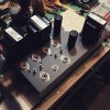
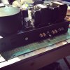
Getting close to finishing it up. Got all the iron mounted last night. Managed to squeeze a can mount for the toroidal transformer in there and fashioned a spacer to leave a 3/16" between the bottom of the can and the rest of the chassis. The can is going to make any active cooling solution much less effective, so I haven't made the final decision on including that yet. Anyway, the transformer is way beefier than this amp requires, so I'm not particularly concerned about it getting too hot.

This beast is HEAVY. I should have made provisions for some internal stiffening of the chassis (gets a little floppier once you start punching holes). But the chassis cover should stiffen it up a bit.
 

Attachments

  • IMG_3490.JPG
    IMG_3490.JPG
    89.3 KB · Views: 41
Looks good. Where did you get the cover for the toroid? How is the cover mounted?

AnTek sells 2 sizes of cans, sized for their transformers. The can itself is a pretty hefty bit of welded steel, with a mounting post in the center that the toroid slips over. It's a sandwich of can, rubber mat, toroid, rubber mat, and a threaded flange that screws onto the mounting post to hold the toroid in place. The mounting post also has a threaded hole that accepts an M8 mounting bolt. The center post is just a bit longer than the sides of the can, to provide a gap between the bottom edge of the can and the metal chassis. I wanted a larger gap, however, due to close proximity of screw heads, etc. So I JB Weld'd together a stack of fender washers to add some extra space, and also used a fender washer below to provide some additional support for the bolt head. I stuffed a small rubber bumper between the can and the choke to ensure that the toroid wouldn't wobble.

My transformer (and AnTek AS-4T320) JUST BARELY fit into the can, and I had to use a bit of gaffer tape to wrangle the transformer leads (one of the more annoying aspects of toroidal transformers, IMO), but it worked out pretty well.

http://www.antekinc.com/ca-400-steel-cover/
 
Here's a shot of the rear of the chassis. From left to right, we have:
  • Power switch
  • IEC power input jack
  • 3.5mm 12V remote turn-on input (fancy Switchcraft jack because I wanted the 12V loop to be completely isolated from the rest of the amplifier and gosh panel-mount 3.5mm connectors that are fully insulated seem to be hard to find)
  • R speaker posts
  • 4 ohm / 8 ohm speaker selector switch (shown in 8 ohm position)
  • L speaker posts
  • R and L input jacks
  • Master input level
The transparent cube-ish thing between the power and output transformers is the remote turn-on relay. The power switch and remote turn-on relay are wired in parallel, so that either one will turn on the amplifier.

As you can see in the photo, I also had to shim up the Hammond transformers (and the choke, as well) with washers below the mounting ears because, unlike the Edcor transformers that I usually use, the rubber grommets protecting the wires as they go through the chassis interfere with the end bells on the Hammonds. This made mounting the iron much more of a pain in the a**.

A few connections left to do under the hood, but that will probably have to wait until the weekend.
 

Attachments

  • IMG_3492.JPG
    IMG_3492.JPG
    59.5 KB · Views: 27
Well, I finished wiring it up tonight, except for the feedback loop (I want to measure the open loop gain first).

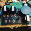
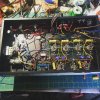
Here's a shot of the underside before I hooked up the input and the screens / plates.

IMG_3495.JPG

One of these days I'll figure out how to do a neat and tidy wiring plan. But it's not actually too bad when it's right in front of you. You can see in the upper-left corner, I went ahead and included the DC fan supply. The connector peeks out of a grommet on the top side. Not sure I'm actually going to use the fan yet, but the connector is pretty innocuous and hardly noticeable even if I decide not to.

Unlike my last build, where I was fast-and-loose with my grounding scheme and got away with it, I was particularly mindful of it this time around. It's primarily a series of star grounds, daisy-chained together with a single earth reference point near the input jacks (the safety ground is connected to the chassis near the IEC connector). The output tubes are grounded via a pseudo-bus that terminates at their filter cap's negative terminal.

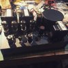
Here's the top side, right after I set the bias / balance controls to get each output tube at 53mA.

IMG_3500.JPG

Tubes are Russian 6П3С-Е, GE 6SN7s (not the final tubes I'm going to use; I have some NOS Silvertone branded RCAs), and Russian 6Н2П.

No signal tests tonight... I need to get up early because my bicycle misses me. I should be able to get started on those tomorrow evening.
 
Okay, hooked it up to the scope and some dummy loads for some initial tests. No NFB or HF tuning currently connected.

First, voltage measurements. The AnTek PT supplies a bit more juice than my original power supply design, so voltages are running a litter higher than I'd planned for / calculated, but not especially so:
  • At first filter cap: 427V
  • At second filter cap (OT supply): 420V (vs 410V)
  • At third filter cap (inverter supply): 411V (vs 400V)
  • At fourth filter cap (AF amp supply): 207V (vs 200V)
As for a few other key measurements:
  • AF amp idle plate voltage: 134V (vs 125V)
  • Inverter idle plate voltage: 284V (vs 279V)
  • Inverter idle grid voltage: 134V (direct-coupled to prior stage)
  • Inverter idle cathode voltage: 139V (vs 130V)
  • Output idle plate voltage: 413V (vs 406V) -- output is ultra-linear connected, so idle screen voltage is essentially the same.
Of note is the inverter... because the cathode is connected to a CCS, which I had pre-set to 9mA (which I verified is still correct), the inverter is likely biased slightly cold for the slightly higher plate voltage. More on that later.

Also balanced and set the output tube bias to 53mA, which gives me -35V on the grids of the outputs. Some are a little higher, some a little lower. I have a bunch of these tubes, so I should shuffle them around looking for better matched pairs.

I connected my function generator to one channel, set it for 1KHz, and adjusted until I saw clipping on the output, and backed it off ever so slightly until the clip went away. 42.8Vpp, which is 15.1Vrms, which into an 8 ohm load is 28.5W.

I backed down the output to 40Vpp, then checked the input: 320mVpp ... Open loop gain is thus 40 / .320 = 125. That's pretty close to what I approximated for the 8 ohm tap (137), based on eyeballing the load line of the output stage. Taking the measurement on the 16 ohm tap (were I'll be taking the feedback from) while an 8 ohm load is on the 8 ohm tap I get 56.4Vpp, so 56.4 / .320 = 176, which again isn't terribly far off my estimation of 196. But this does change my feedback calculation somewhat. Leaving the circuit as-is, I'll have -11dB instead of -11.6dB.

To check the voltage swing to the output tubes, I set it to max power and connected the scope to the grid of one output tube. I get 68Vpp. At 71Vpp, I start to see the peak of the wave clip, while the valley maintains its shape. This is why I suspect the inverter stage is biased incorrectly. I also notice that one of these GE 6SN7s has a weaker half; this probably also explains why the valley of the output clips before the peak does. Guess I should tube roll before I really dial this thing in.

1KHz square waves @ 1W aren't terrible looking. Again, pre-feedback.

Connected to speakers, it sounds pretty good with music playing though it. I played my usual test tracks and they all sound good at low and high volumes.

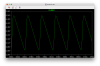
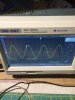
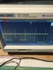
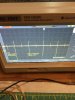
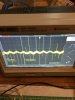
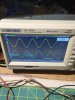
I am noticing some noise coming though the speakers, though, and I caught a glimpse of it on the scope. After hearing it, I decided to look at it on the scope with no input signal. As you can see from the photo (#1), it's not hum. The sound is a very regular sharp popping sound. Some of it is definitely environmental noise -- which I switch off my (LED) desk lamp, the small "beads" in that wave form go away (photo #2, #3), but the large spikes remain. As you can see, it's worst with the input pot set at max (photo #4), but certainly not awesome with it set at min (photo #5). It's cleanest with the input put set at about 25%. It's definitely present in the signal coming FROM the phase inverter (measured at the output tube grids). Not sure how I can measure the signal being sent TO the inverter, since it's direct-coupled. (I'm not even sure if it's "safe" to pull the first stage tube out, because it's direct-coupled to the inverter.)

 

Attachments

  • IMG_3503.JPG
    IMG_3503.JPG
    55.1 KB · Views: 10
  • IMG_3505.JPG
    IMG_3505.JPG
    56.3 KB · Views: 9
  • IMG_3506.JPG
    IMG_3506.JPG
    58.9 KB · Views: 9
  • IMG_3508.JPG
    IMG_3508.JPG
    56.1 KB · Views: 11
  • IMG_3509.JPG
    IMG_3509.JPG
    57 KB · Views: 9
So, just out of curiosity, I decided to jumper in the feedback resistor. It didn't behave at all like I expected.

When connected, I expected the output to drop from 8Vpp to a bit more than 2Vpp. Instead the output stayed solid, but that audible sound of the tubes became noticeably louder (you know the sound, when you're pumping a test tone through the tubes full-bore into a dummy load). With music, it made it sound tinny -- took away all the bass response.

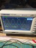
I verified the phasing... Photo #1, yellow trace is 8 ohm tap on the OT, blue trace is input from signal generator. As previously discussed in another thread, you want NFB to the cathode to be IN PHASE with the input because the gain stage amplifies the difference between the cathode and the grid.

Photo #2, yellow trace is voltage at the feedback divider, blue trace is input from signal generator. Same voltage scale.

Interestingly enough, if I remove the ground reference for the OT secondary, the feedback loop behaves more like I would expect. Reduction in gain and the frequency response seems to flatten out (though bass response still seems reduced, which is counter-intuitive to me).

And then there's "connect feedback loop of both channels". That just causes the amp to oscillate like crazy. One connected? Fine. Both connected, *SQUEEAAAAAL*.

So this has me stumped.
 

Attachments

  • IMG_3510.JPG
    IMG_3510.JPG
    60.2 KB · Views: 6
  • IMG_3511.JPG
    IMG_3511.JPG
    59.7 KB · Views: 4
Last edited:
Can you post your latest schematic--both power supply and audio amp together?

Larger output when feedback applied sure sounds like you have positive feedback going on instead of negative feedback. Try reversing the tubes your plate and UL lead pairs are connected to, or it's a transformer factory wiring error (doubtful with Hammond, but I suppose possible). I'd probably just validate those OPTs for correct lead outs before getting too deep into the debugging.
 
Attached is a PDF copy of the current schematic, annotated with measured voltages and the open loop gain.

I was thinking "positive feedback" as well, but the scope seems to say otherwise. In any case, I did do a quick check of the primary leads with a meter. See also attached Hammond tech sheet.

Here are the resistance measurements:
  • RED - BLU = 66 ohms
  • RED - BLU/YEL = 30 ohms
  • RED - BRN = 74 ohms
  • RED - BRN/YEL = 27 ohms
  • BLU - BRN = 140 ohms
  • BLU - BLU/YEL = 35 ohms
  • BLU - BRN/YEL = 93 ohms
  • BRN - BRN/YEL = 47 ohms
So, from that we can infer that the leads on the primary are tapped correctly.

The DC resistance of the secondary is, of course, really low, but it seems correct... BLK to WHT, YEL, GRN is 0.5 ohms, 0.4 ohms, and 0.3 ohms, respectively.

For the final test, I connected my signal generator + to BLU and - to BRN, along with my yellow scope probe. Blue scope probe was then connected to WHT and BLK. The signals are 180deg out of phase, as per the Hammond data sheet (see phasing dot).

So, I think the transformers check out OK.
 

Attachments

Ok, putting aside the feedback issue for now... I decided to focus on the more pressing problem -- the buzzing noise I mentioned in post #135.

I removed the shielded wire to get the input pot and jacks out of the equation, and grounded the 6N2P's grids with alligator wires.

Using speakers instead of dummy loads, I poked around with a chopstick to see if I could hear any changes. Nada. Using the 10X setting on my scope probe, I looked at the grid of the 6SN7s... It doesn't seem like the noise is coming from the 6N2P, and I tried a different tube there just to be sure. Unfortunately, because the stage is DC-coupled, it's kind of hard to get my scope dialed in to look at it with a small scale. The noise is definitely present on the grids of the outputs, though, so it's definitely coming from one of the front-end stages.

I did notice that the noise is coming much more from the R channel than the L channel. I determined this by briefly removing the speaker cable from one side at a time. It's VERY pronounced on the R channel, and not-exactly-faint-but-a-whole-lot-less on the L channel.

For kicks, I swapped in another 6SN7 at that position -- no change. I moved the CCS board -- no change. I swapped CCS sides -- no change. Taking a break from it to stew on it for a bit... but would appreciate suggestions of diagnostic steps to try.
 
Is it a typo on your schematic that the grid of the second triode in your phase inverter is not properly biased? (no high impedance resistor from grid 1 to grid 2).
 
Back
Top Bottom