You are using an out of date browser. It may not display this or other websites correctly.
You should upgrade or use an alternative browser.
You should upgrade or use an alternative browser.
Brainstorming a push-pull 6L6GC stereo amp
- Thread starter thorpej
- Start date
-
- Tags
- 6l6gc push pull ultra linear

jazbo8
Well-Known Member
There are some typo's on the schematic, the plate voltages of the differential amplifier are too high, and the stage's gain of 1.8x should be changed to 7 (per side). The above open loop gain calculation appears to be based on the DC load only (27k), perhaps that's close enough for an estimate.
Last edited:

There are some typo's on the schematic, the plate voltages of the differential amplifier are too high, and the stage's gain of 1.8x should be changed to 7 (per side). The above open loop gain calculation appears to be based on the DC load only (27k), perhaps that's close enough for an estimate.
Thanks for pointing out the error on the 6SN7 plate voltages. Not sure where I got that number from... I can only assume that I typed it late at night when I really should have been sleeping. I've corrected the schematic and attached an updated version.
Good point on the fact that I only provided a DC load line. For the 12AX7, I don't think it changes much ... DC-coupled, and a 1M AC ground path doesn't change it too much. As far as for the 6SN7, the total ground return resistance for AC is right around 90K when you account for the bias adjustment network, which means the AC load is about 20.7K. This does make the line a bit steeper, but not hugely so. However, the DC load line would indicate a gain (a tad over 15) larger than what I've calculated -- I ran the numbers through the equations using 75K as the next stage grid return to get a gain of 14, which I then halved because differential pair, hence 7. If I run the numbers through the calculator using 1M for the next stage grid return, out pops the tad-over-15 that the load line shows... So, I think I've got the true AC load accounted for.
Attachments
This evening I spent some time trying to economize the power supply. The first version, which used separate LC filters for each output stage, had a couple of problems:
The risk is that I end up with voltages a little lower than anticipated... but it's worth the reward of reduced component count and better filtering for the inverter, I think.
- 2 not terribly attractive-looking filter chokes
- layout difficulties due to the 2 aforementioned chokes plus the associated can caps
- Insufficient filtering of the inverter's supply
The risk is that I end up with voltages a little lower than anticipated... but it's worth the reward of reduced component count and better filtering for the inverter, I think.
Attachments

Seems like a reasonable tradeoff. The only other thing I can think of to simplify the power supply is to ditch the voltage quadrupler, but I know you are relegated to that topology given the choice of your power transformer.
Just some quick sanity checks, at 78V secondary, DC filtered voltage out to the high side of your filter choke looks to me to be about 405V (78VAC x 1.3 x 4), but if it's an older power transformer where the primary was wound for 110V or 115V instead of 120V, it may be moot. I used very similar voltages on an amp I built with 1625 outputs (6L6 types), that were UL connected, and using Hammond 1650H OPTs, and I was still able to get a clean 20 watts output, so it should be okay.
If you do end up using the newer Hammond 1650HA's for your OPTs, I will be very curious to see how they perform. Traditionally, the regular 1650H's (not the HA's) have quite good low end performance, but they have some HF resonances in the 30KHz to 60 KHz range that require diligence in the HF tuning of the amp to minimize or eliminate. The 1650H's (not the HA's), use an interleaving method that allows only one impedance configuration of your choice of 4, 8 or 16 ohms to be used. The HA's I think use a more traditional secondary with one larger wind and with taps for 4 and 8 ohms. I'm just guessing this will change the HF and resonant characteristics slightly--hopefully for the better over the regular 1650H's.
Just some quick sanity checks, at 78V secondary, DC filtered voltage out to the high side of your filter choke looks to me to be about 405V (78VAC x 1.3 x 4), but if it's an older power transformer where the primary was wound for 110V or 115V instead of 120V, it may be moot. I used very similar voltages on an amp I built with 1625 outputs (6L6 types), that were UL connected, and using Hammond 1650H OPTs, and I was still able to get a clean 20 watts output, so it should be okay.
If you do end up using the newer Hammond 1650HA's for your OPTs, I will be very curious to see how they perform. Traditionally, the regular 1650H's (not the HA's) have quite good low end performance, but they have some HF resonances in the 30KHz to 60 KHz range that require diligence in the HF tuning of the amp to minimize or eliminate. The 1650H's (not the HA's), use an interleaving method that allows only one impedance configuration of your choice of 4, 8 or 16 ohms to be used. The HA's I think use a more traditional secondary with one larger wind and with taps for 4 and 8 ohms. I'm just guessing this will change the HF and resonant characteristics slightly--hopefully for the better over the regular 1650H's.

PakProtector
AK member
To do this properly, you need to search out a family of plate curves that is based on UL operation, with the screen tapped at the point that you intend to use. Such curves exist, and do in fact look like a compromise between pentode and triode plate curves.
Dave
It is worse than that Dave, the curves must also *START* at the B+ you intend to use. For an AB1 operating point, this is perhaps easier to find...for a Class A operating point, forget about it.
cheers,
Douglas
Seems like a reasonable tradeoff. The only other thing I can think of to simplify the power supply is to ditch the voltage quadrupler, but I know you are relegated to that topology given the choice of your power transformer.
Yah, this PT is a little silly, but part of the fun is seeing what I can build with it. They were so hard to resist considering what I paid for them

Just some quick sanity checks, at 78V secondary, DC filtered voltage out to the high side of your filter choke looks to me to be about 405V (78VAC x 1.3 x 4), but if it's an older power transformer where the primary was wound for 110V or 115V instead of 120V, it may be moot. I used very similar voltages on an amp I built with 1625 outputs (6L6 types), that were UL connected, and using Hammond 1650H OPTs, and I was still able to get a clean 20 watts output, so it should be okay.
It's not entirely obvious on the schematic, but here's the scoop with the transformer... The secondary is 67VCT. The primary has connections for 120VAC (US) or 100VAC (Japan). Connecting US 120V mains to the 100VAC primary yields 78VAC on the secondary.
If you do end up using the newer Hammond 1650HA's for your OPTs, I will be very curious to see how they perform. Traditionally, the regular 1650H's (not the HA's) have quite good low end performance, but they have some HF resonances in the 30KHz to 60 KHz range that require diligence in the HF tuning of the amp to minimize or eliminate. The 1650H's (not the HA's), use an interleaving method that allows only one impedance configuration of your choice of 4, 8 or 16 ohms to be used. The HA's I think use a more traditional secondary with one larger wind and with taps for 4 and 8 ohms. I'm just guessing this will change the HF and resonant characteristics slightly--hopefully for the better over the regular 1650H's.
I'm sure I'll start a whole other thread about HF tuning once I get the thing build
Seems like a reasonable tradeoff. The only other thing I can think of to simplify the power supply is to ditch the voltage quadrupler, but I know you are relegated to that topology given the choice of your power transformer.
Well, I managed to economize a bit further, just by changing the other two transformers in the power supply For the bias supply, using a Triad F4-120 saves $20 over the Hammond I had listed before (I could probably get away with the F3-120, but it's only like $2 cheaper). Since it's just the bias supply, a 50mA-rated transformer should be quite adequate. And then again using a Triad F-18X for the heater supply shaves off another $10 compared to the same-rated 6.3V 6A Hammond I had specified before. These transformers are small enough that they'll mount neatly below the chassis.
Annoyingly, Hammond makes a dual secondary 120V / 6.3V that would do the trick, except the 6.3V winding is only rated at 1.5A.
Ok! This project is not dead! In fact, I'm gearing up to build it this summer. I plan to use this amp in the main system in the living room of our freshly-remodeled house. My Yamaha AV receiver is nice and all, but as our system has evolved over the years, it's also become increasingly complicated to actually USE it (which bugs my wife to no end), and so I'm taking this opportunity to simplify.
I am planning to pair the amplifier with a Parasound 2100 pre-amp in order to get the basic creature comforts. The 2100 features a 12v (150ma max) power control loop that can be used to power on downstream equipment.
My thought was to install an additional octal socket and use the 12v flavor of this guy: http://www.parts-express.com/pedocs/specs/kest-kir2p-series-specifications.pdf
To use this, it looks to me like I'd attach the 12v control feed to pins 2 and 7, the power transformer primary to pins 8 and 1, and the mains hot and neutral to pins 3 and 6, respectively. I would probably also wire the front panel power switch in parallel to the relay so that I could turn it on without using the control loop.
Has anyone here ever added a power control loop like this to one of their projects? Any gotchas to watch out for?
I am planning to pair the amplifier with a Parasound 2100 pre-amp in order to get the basic creature comforts. The 2100 features a 12v (150ma max) power control loop that can be used to power on downstream equipment.
My thought was to install an additional octal socket and use the 12v flavor of this guy: http://www.parts-express.com/pedocs/specs/kest-kir2p-series-specifications.pdf
To use this, it looks to me like I'd attach the 12v control feed to pins 2 and 7, the power transformer primary to pins 8 and 1, and the mains hot and neutral to pins 3 and 6, respectively. I would probably also wire the front panel power switch in parallel to the relay so that I could turn it on without using the control loop.
Has anyone here ever added a power control loop like this to one of their projects? Any gotchas to watch out for?
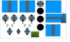
Here is the layout I plan to use. Mildly concerned that the bias supply transformer is parallel to the choke, but it's below deck and isn't drawing much current, so hopefully won't make too much noise. Anyone see any issues with how things are arranged? Chassis is 17x10.
Attachments
Last edited:
The bias transformer and the choke in my Bogen 100A's are side by side, aligned cores and sharing a mounting hole. It doesn't seem to cause any trouble.
If you can scoot that first filter cap away from the rectifier a bit, it wouldn't hurt the cap's feelings any.
Thanks for the sanity check on the choke placement. I was going back and forth trying to figure out what I wanted to do, and this was the best I could come up with. Downside is that a non-pretty transformer is on the top side, but with the perforated cover on the amp, no one will ever notice, I don't think. I suppose I could always paint it.
FWIW, that socketed thing behind the first filter cap is actually a socketed relay for supporting remote turn-on via a 12v control loop. All of the rectifier diodes are below the chassis (along with 2 additional filter caps).
Oh, one thing I forgot to ask about before... is there anything I need to worry about vis a vis the orientation of the main PT (which has a lay-down mount)? I suppose I should draw on the diagram where the copper flux band is, in case it matters...

OK, nevermind then. Thought you had a 5AR4 stuck back there or something. If its not making heat, it won't bother it any.
If the core on the power transformer is horizontal and the outputs vertical, that should be all you need. It just needs to be 90 degrees relative to each other, whichever direction that 90 happens to come from.
I didn't so much want to put those parts next to one another on the Bogen, it just happened to be the only place I could stuff them. I sort of crossed my fingers and hoped for the best.
If the core on the power transformer is horizontal and the outputs vertical, that should be all you need. It just needs to be 90 degrees relative to each other, whichever direction that 90 happens to come from.
I didn't so much want to put those parts next to one another on the Bogen, it just happened to be the only place I could stuff them. I sort of crossed my fingers and hoped for the best.
Started working on the CCS board last night... just fiddling with the layout right now. I think I'll probably end up rotating one of the 10M45s 180 degrees to make the K connection a bit more direct, but I have to decide if the symmetrical look is more important
Attachments
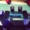
Built the CCS board tonight. Sure wish my eyesight was better Anyway, it seems to work correctly. I have the K pin connected to ground via a 10 ohm 1% resistor and 1K trim pot. I hooked it up to a 12V wall wart and adjusted the pot until I got 0.090V across the 10 ohm resistor for my target of 9mA of constant current. From the chart on 10M45 data sheet, I ball-parked 300 ohms of resistance required to set 9mA, and after setting the current to 9mA I measured 329 ohms between K and ground, so it behaved just as I expected.
Of course, I realized after I finished it that I got one of the heat sinks too close to a mounting hole, so I'm going to have to use nylon screws to attach the board to the stand-offs, but that's not a big deal.
Anyway, it seems to work correctly. I have the K pin connected to ground via a 10 ohm 1% resistor and 1K trim pot. I hooked it up to a 12V wall wart and adjusted the pot until I got 0.090V across the 10 ohm resistor for my target of 9mA of constant current. From the chart on 10M45 data sheet, I ball-parked 300 ohms of resistance required to set 9mA, and after setting the current to 9mA I measured 329 ohms between K and ground, so it behaved just as I expected.Of course, I realized after I finished it that I got one of the heat sinks too close to a mounting hole, so I'm going to have to use nylon screws to attach the board to the stand-offs, but that's not a big deal.