• The move to the new server is done. There are some software and database maintenance updates in process. This has us passing the hat around to help out. We appreciate any donations. Seriously, even a dollar helps. The payment page may be found here - https://www.audiokarma.org/support.html

Brainstorming a push-pull 6L6GC stereo amp

Thorpej -- If I may, I would offer a few points for your consideration in your project:

1. As long as the bias control circuit in total (that is, including all the controls associated with it) has enough current flowing through all of its supply points (where the grid return resistors attach to) under any combination of control settings, then the complete bias circuit can be considered as being "invisible" with respect to your concerns for the total amount of grid no.1 dc resistance for your output tubes, as in effect such current flow provides a virtual ground relative to any reverse grid current the tubes might develop. A virtual ground will be achieved as long as each supply point is flowing at least 1 ma for any control setting. The bias circuit of the HF-89 does not normally draw that much current, but in that case, the total grid no. 1 resistance including that of the bias adjustment circuit was still within the recommendations of the tube manufacturers for the EL34, so the concerns were minimized. The best way to alter the circuit for use with 6L6 class tubes is to up the current through the bias adjustment circuit appropriately, and then set your grid return resistance as you will within the recommended range.

2. 6SN7 class tubes are perfectly capable of driving 6L6 class tubes to full power output under conditions of high bias in the output stage, and with low distortion too -- but for the most practical results, should use 47K plate load resistors to do so. Eico used the same inverter values as found in the HF-89 in their HF-22 design as well. In that circuit, the 6L6s operate with cathode bias with lower average bias voltage at full power output than you will be using under quiescent conditions in your project, and the inverter as originally designed struggles in that model under full power conditions at low frequencies. Oh the original Eico design can do it if you want to seriously up the current flow through the inverter tube. But all you'll really be dong is shortening the life of the tube, whereas raising the value of the plate load resistors coupled with a modest increase in current flow will accomplish the same thing much more effectively, and the tube will last much longer.

3. If you are planning the operate your output tubes in UL, then the optimum plate-to-plate load for 6L6 class tubes when using fixed bias is 6600 Ohms. Any lower value -- even a value of 6000 Ohms compromises HF performance. You will often see these tubes with this plate load value operating with cathode bias -- but if such designs are performance tested, their THD and IMD numbers will be found to be quite elevated. However, using fixed bias with these tubes and this loading condition, in this mode of operation, will produce very low levels of distortion, and produce wonderful performance across the full audio spectrum. The optimum UL tap is 43%, although 40% is certainly acceptable. With a capable OPT and about 450 vdc of B+, the tubes can develop about 30-32 watts RMS into a secondary load, and deliver very high quality performance.

Good luck with your project!

Dave
 
1 More point. Eico's were all kits assembled by amateurs, their lay out was not fussy and they worked great...Most the Eico's I've had were poorly wired, had crappy soldering and obivious mistakes in assembly. But Sounded Wonderfull
 
Thorpej -- If I may, I would offer a few points for your consideration in your project:

Thanks for chiming in Dave!

1. As long as the bias control circuit in total (that is, including all the controls associated with it) has enough current flowing through all of its supply points (where the grid return resistors attach to) under any combination of control settings, then the complete bias circuit can be considered as being "invisible" with respect to your concerns for the total amount of grid no.1 dc resistance for your output tubes, as in effect such current flow provides a virtual ground relative to any reverse grid current the tubes might develop. A virtual ground will be achieved as long as each supply point is flowing at least 1 ma for any control setting. The bias circuit of the HF-89 does not normally draw that much current, but in that case, the total grid no. 1 resistance including that of the bias adjustment circuit was still within the recommendations of the tube manufacturers for the EL34, so the concerns were minimized. The best way to alter the circuit for use with 6L6 class tubes is to up the current through the bias adjustment circuit appropriately, and then set your grid return resistance as you will within the recommended range.

Right, so I interpret that as "use smaller resistors and pots in the divider / control network", such that the voltage .. uh .. drop? results in at least 1ma of current at the tie point for each P-P pair. Have I got that right? I think I'm going to model my bias supply more after the one in the Dynaco ST-70 -- it seems a little more straight-forward -- but I still plan to use a balancing network a'la the HF-89.

3. If you are planning the operate your output tubes in UL, then the optimum plate-to-plate load for 6L6 class tubes when using fixed bias is 6600 Ohms. Any lower value -- even a value of 6000 Ohms compromises HF performance. You will often see these tubes with this plate load value operating with cathode bias -- but if such designs are performance tested, their THD and IMD numbers will be found to be quite elevated. However, using fixed bias with these tubes and this loading condition, in this mode of operation, will produce very low levels of distortion, and produce wonderful performance across the full audio spectrum. The optimum UL tap is 43%, although 40% is certainly acceptable. With a capable OPT and about 450 vdc of B+, the tubes can develop about 30-32 watts RMS into a secondary load, and deliver very high quality performance.

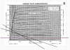
Good info, thanks. Also, good segueway into the next topic that's confusing me... drawing up load lines and determining the ballpark bias point for this thing. In the Keroes "Design and Theory..." article, one is led to believe that the plate characteristics curves for UL operation look, in principle, more like the triode curves. In any case, because the screen is going to modulate, it's logical that they won't look like the pentode curves.

So, the GE 6L6GC data sheet I'm using has 2 plate characteristics graphs, one for 250V screens, one for 400V screens, the latter neatly matching what I expect to have after filtering losses. I drew my load lines on the 400V screen graph, and picked a 53ma idle starting point, just to get me an idea of what my bias requirements would be. This gave me approximately -40V. This is pretty close to the -37V in the data sheet's class AB1 typical operation table for a 450V plate / 400V screen / 5600 load pentode connection with 58ma idle per tube.

I'm hoping this was the right approach (or at least, close to :-) ).

Screen Shot 2016-02-02 at 3.05.58 PM.png

Good luck with your project!

Dave

Thanks! I probably won't build it until much later this year, but I'll probably build little parts of it (like the 4x voltage multiplier, the CCS circuits, the bias balancing networks) on perf boards over the course of the year and have my kids build them with me. Should be loads of fun!
 
To do this properly, you need to search out a family of plate curves that is based on UL operation, with the screen tapped at the point that you intend to use. Such curves exist, and do in fact look like a compromise between pentode and triode plate curves.

Dave
 
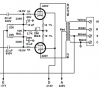
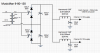
One more thing to consider when you design your bias/balance scheme (I assume you are going with bias/balance instead of individual bias for each tube): you can wire it up in such a way so that if the adjust pots ever do go south (usually wiper disconnecting from the track), it won't cause the tubes to lose bias and red plate the tubes. I actually got this hint a while back from Dave, so this is not my idea really. What you do is wire the DC balance pot so that the wiper feeds the bias pot, instead of the balance pot wiper receiving the raw bias voltage like almost all other amps do it. Like this (snipped from the schematic of the amp I just finished based on the Fisher 400).

upload_2016-2-2_17-49-36.png

By the way, one thing I would do differently if I were building that amp again is to use smaller pot sizes, maybe a 5K bal pot and an 10K bias pot, and adjust the resistors in the network accordingly to give me close to the same voltage swings. With the 7868 tubes being higher in transconductance than say a 6L6, the adjustments are a little touchy.
 
Last edited:
To do this properly, you need to search out a family of plate curves that is based on UL operation, with the screen tapped at the point that you intend to use. Such curves exist, and do in fact look like a compromise between pentode and triode plate curves.

Dave

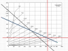
Now why didn't I think of that. Sure enough, I found one ... although it's not quite what I'm looking for... this is 450V 43%, but I think it's a good point to start with.

Here are the load lines I drew for 400V / 6600 ohm:

Screen Shot 2016-02-02 at 5.40.04 PM.png

As you can see, it kind of falls apart at the 0V curve... I eyeballed it at 450V / 6600 ohm, and that would pass just above the knee at 0V. Unfortunately, the PT I have for this project won't do that, so it'll be a bit of a compromise. I'll also be at 400V, not 450V, so perhaps that curve will slide down and bit and get me closer to the knee of the curve when we hit 0V.
 
As you can see, it kind of falls apart at the 0V curve... I eyeballed it at 450V / 6600 ohm, and that would pass just above the knee at 0V. Unfortunately, the PT I have for this project won't do that, so it'll be a bit of a compromise. I'll also be at 400V, not 450V, so perhaps that curve will slide down and bit and get me closer to the knee of the curve when we hit 0V.

Happily, the web site I grabbed that 6L6 UL curve graph from also had one for an 807 at 400V! I drew up another set of load lines on that graph, and as I hoped, the 0V curve has slid down to a much happier spot for the Class B line. Hooray! It also jives pretty well with the 6L6GC data sheet for 450V / 400V operation in terms of the bias point.

Screen Shot 2016-02-02 at 8.18.47 PM.png
 
One more thing to consider when you design your bias/balance scheme (I assume you are going with bias/balance instead of individual bias for each tube): you can wire it up in such a way so that if the adjust pots ever do go south (usually wiper disconnecting from the track), it won't cause the tubes to lose bias and red plate the tubes. I actually got this hint a while back from Dave, so this is not my idea really. What you do is wire the DC balance pot so that the wiper feeds the bias pot, instead of the balance pot wiper receiving the raw bias voltage like almost all other amps do it. Like this (snipped from the schematic of the amp I just finished based on the Fisher 400).

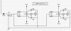
Yah, that's good advice. I actually did the same tweak to my SE 6L6 schematic the other day (just finished punching / cutting the chassis for that one, now just waiting for the transformers to arrive!):

Screen Shot 2016-02-02 at 8.44.32 PM.png

Connect the in-and-out to either end of the pot, and connect the shunt to the side that you want to be the "turned all the way up" side.

By the way, one thing I would do differently if I were building that amp again is to use smaller pot sizes, maybe a 5K bal pot and an 10K bias pot, and adjust the resistors in the network accordingly to give me close to the same voltage swings. With the 7868 tubes being higher in transconductance than say a 6L6, the adjustments are a little touchy.

I figure the current thought the bias circuit is low enough that one of those 20-turn trim pots would be good for the balance network, especially considering how non-linear it gets as you veer away from the center.

I need to sit down and learn how to use MacSpice so I can simulate the power supply and bias circuit properly.
 
One more thing to consider when you design your bias/balance scheme (I assume you are going with bias/balance instead of individual bias for each tube): you can wire it up in such a way so that if the adjust pots ever do go south (usually wiper disconnecting from the track), it won't cause the tubes to lose bias and red plate the tubes. I actually got this hint a while back from Dave, so this is not my idea really. What you do is wire the DC balance pot so that the wiper feeds the bias pot, instead of the balance pot wiper receiving the raw bias voltage like almost all other amps do it. Like this (snipped from the schematic of the amp I just finished based on the Fisher 400).

Thanks for posting that schematic snippet. And thanks @jazbo8 for the LTspice suggestion... I've never used any of the SPICEs before, but I was able to figure it out while I ate my lunch at my desk today (sometimes continuing education requires being a bit anti-social, I suppose). Their Mac version is a bit different than their Windows version, but once I figured out where stuff was hidden I was able to make it go.

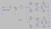
Anyway, had some time to fiddle on the bias circuit while on the bus ride home from work and managed to put one together that seems like it will work.

Screen Shot 2016-02-04 at 8.19.48 PM.png

My PT puts out 78Vrms. For B+, I am planning to use 4x voltage multiplier across the entire winding (it's center-tapped, but I will leave that unused). I *think* that I can then just tap one leg of the secondary winding to use for my bias supply, yes? I have to admit that I'm a bit worried about the voltage reference. I suppose I'll just have to put the entire thing together in the simulator :)

Well, hopefully that would give me -109V peak though the diode. In the simulation I specified an AC voltage source with a 109V amplitude (I didn't see a way to specify Vrms).

So, given those input parameters, the above circuit with all controls centered, gives me -36V at each of the bias tap points. With balance centered, the bias voltage range is -31.5V to -41V. With the bias control centered and the balance pot turned to one extreme, there is a 7V difference between either side (e.g. A-B).

EDIT: Oops! Simulator says "No!". My concern was warranted. Back to the drawing board, I guess!
 
Last edited:
Do you have a filament winding, either 5V, 6.3V, or 12.6V on your power transformer? If you do, you can obtain some bias voltage by running an external small filament transformer backwards. For example using a 120V:6.3V filament transformer and connecting the 5V winding on the power transformer to the 6.3V winding on the filament transformer will give you about 80VAC out on the 120V primary side. Another tip I received a while back from the good folks here. ;)
 
Do you have a filament winding, either 5V, 6.3V, or 12.6V on your power transformer? If you do, you can obtain some bias voltage by running an external small filament transformer backwards. For example using a 120V:6.3V filament transformer and connecting the 5V winding on the power transformer to the 6.3V winding on the filament transformer will give you about 80VAC out on the 120V primary side. Another tip I received a while back from the good folks here. ;)

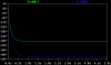
I don't (the PT I'm using was originally for a solid-state), but that's a great idea! AES carries a low-current 6.3V PT for less than $10. I need a 6.3V 6A PT anyway, I'll just toss another one on there. Just real quick I tweaked and simulated the bias supply for that scenario, and came up with this (plot shows one channel at each of the extremes... centered it's ~-36V).

Screen Shot 2016-02-04 at 11.07.38 PM.png Screen Shot 2016-02-04 at 11.07.51 PM.png
 
Glad to see that you got LTSpice working on your Mac, it is not as good as the PC version, but could probably get the job done in most cases. There are some sym and sub files available for the potentiometer if you want to do DC sweep analysis without having to adjust the resistors manually.
 
That looks good except running a 120V:6.3V transformer in reverse is about 83% efficient.
 
Last edited:
That looks good except running a 120V:6.3V transformer in reverse is about 83% efficient.

Yah, I may just look for a small 120V-120V isolation transformer instead. Hammond 166F120 fits the bill (115V-120VCT). Or I could use the 166G80 (115V-80VCT) with the previous values. There are options, anyway.
 
Last edited:
Well, in the mean time, I fleshed out the voltage multiplier and filter stage of the power supply.

Screen Shot 2016-02-05 at 1.49.08 PM.png

The absurdly large caps are there to keep the plate / screen supply from sagging too far at full power (ballpark 250mA per channel). I will definitely be using a thermistor on the PT primary to limit the inrush current. At the end of channel 1's power rail will be a voltage divider to provide 35V of heater elevation, that will also act as a bleeder. Channel 2 will simply get a bleeder of equal value.

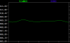
Zoomed in, it's a little wavy at 150mA per channel, but not too awful:

Screen Shot 2016-02-05 at 8.33.35 PM.png

This is what it looks like at full power (zoomed a bit further in). Flatter? ¯\_(ツ)_/¯

Screen Shot 2016-02-05 at 8.35.17 PM.png
 
Well, in the mean time, I fleshed out the voltage multiplier and filter stage of the power supply.
Please take a look at the voltage across the capacitors and the diodes with the sim. I'm not sure where to get 800uF capacitors with the proper voltage rating. I guess you will have to do some series and parallel combinations.
 
Last edited:
I'm not sure where to get 800uF capacitors with the proper voltage rating.

Digi-Key and Mouser have plenty of capacitor choices in this voltage and capacitance range but they will be the snap-in style rather than having leads.
 
Digi-Key and Mouser have plenty of capacitor choices in this voltage and capacitance range but they will be the snap-in style rather than having leads.
They are certainly not cheap...:eek: and the only one in stock at Mouser.

mouser.png
 
Back
Top Bottom