

You are using an out of date browser. It may not display this or other websites correctly.
You should upgrade or use an alternative browser.
You should upgrade or use an alternative browser.
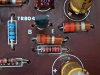

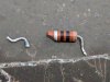
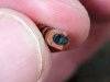
Fixed! Finally. R812 might have had some visible cracks but it wasn't the problem. Pic below is R842 - 10ohm. One leg fell off when I was pulling it off the board and looks like maybe some scorching in there. I redid the baxandall diode mod, put the WIMA cap that I temporarily replaced back in, and re-set the AC bias. Now both channels are pretty close in voltage and output power. 25.7 watts output on both channels with no clipping.

Well done!!
Thanks. This has been a real learning experience for me.Well done!!

Blue Shadow
Waiting for Vintage Gear from this century
I dropped in to see what the AU-555 looks like since a TU just sold from BT.
But I didn't see any pics of the unit, just restoration pics. NBD there are pics of this unit out on the web somewhere.
Looking at those fuse holders and the need for hard-to-find fuses:
did you find the right size to fit the holders?
is one of the holders bent or twisted or soldered in place wrong as one fuse still looks crooked
I might grab some fuse holders like are used in this amp and mount them to allow use of a commonly available fuse like the 5x20. This would require replacing all four but they are cheap parts. Then fuse swaps would be easy.
Nice work. Finding that resistor must have been a relief.
But I didn't see any pics of the unit, just restoration pics. NBD there are pics of this unit out on the web somewhere.
Looking at those fuse holders and the need for hard-to-find fuses:
did you find the right size to fit the holders?
is one of the holders bent or twisted or soldered in place wrong as one fuse still looks crooked
I might grab some fuse holders like are used in this amp and mount them to allow use of a commonly available fuse like the 5x20. This would require replacing all four but they are cheap parts. Then fuse swaps would be easy.
Nice work. Finding that resistor must have been a relief.
Thanks. This has been a real learning experience for me.
All we need now is your listening impressions after all this effort
Last edited:
I dropped in to see what the AU-555 looks like since a TU just sold from BT.
But I didn't see any pics of the unit, just restoration pics. NBD there are pics of this unit out on the web somewhere.
Looking at those fuse holders and the need for hard-to-find fuses:
did you find the right size to fit the holders?
is one of the holders bent or twisted or soldered in place wrong as one fuse still looks crooked
I might grab some fuse holders like are used in this amp and mount them to allow use of a commonly available fuse like the 5x20. This would require replacing all four but they are cheap parts. Then fuse swaps would be easy.
Nice work. Finding that resistor must have been a relief.
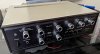
I just happened to put all the covers back on it after I got the alignment done. I haven't seen it except in a pile of parts since the day I got it so I thought I'd put it back together for a while. I put a pic of it below but you'll find plenty more on the internet too.
The fuses are a little harder to find but they're available and I got some from Mouser. Probably all the usual other places have them too. They're AGX size which is 1/4" x 1". My fuse holders were a little tweaked. I tried to straighten them out a bit but they're still not perfect. The connections are still good so I'm living with it.
Lot of those carbon teaistors
All we need now is your listening impressions after all this effort
It sounds great! I listened to some of my favorites today. Songs I'm very familiar with from lots of different genres. Everything sounds great on it.


Leestereo
Super Member
... Pic below is R842 - 10ohm. One leg fell off when I was pulling it off the board and looks like maybe some scorching in there...
The R841 and R842 resistors are part of the output zobel for the left and right channels, respectively. In the 555, the stock resistors are rated at 0.5W and this is, IMO, too low; better to use a 2W or 3W resistor for function (e.g., the 555A uses has a 6.8ohm 3W resistor).
That's very interesting. Now I have to go read on Zobel networks. And start putting together parts order # (checks notes) 6. Is it worth up-rating any other resistors? I imagine the 10 ohm one is carrying most of the current so it makes sense if that's the one that really needs up-rating I guess.The R841 and R842 resistors are part of the output zobel for the left and right channels, respectively. In the 555, the stock resistors are rated at 0.5W and this is, IMO, too low; better to use a 2W or 3W resistor for function (e.g., the 555A uses has a 6.8ohm 3W resistor).
Last edited:

Great job sticking with it @Brian1970
Since I need to order at least a couple bigger resistors anyway, I might get what I need to switch the power-on lamp to an LED. The original lamp still works but who knows for how much longer and it makes a lot of unnecessary heat. I think a green LED will look good and match the green script on the faceplate. I'll have to rectify the 6.3VAC going to the bulb now but that won't be too big a deal. Since the LED will be attached to the faceplate, I'll need a small connector that can fit through the hole in the chassis so the faceplate can remain removable. I found a good post by EchoWars explaining how to do the rectification and figure out the current limiting resistor value. https://audiokarma.org/forums/index...ight-replacement-project.119597/#post-1263366

sylfi
New Member
Hi ! I own a sansui au-555 restored(nichicon caps) who sing wonderfully with my kef 104/2, but the 2200uf from 1969 are still in place…
Do you you recommend 6800uf or 2200uf nichicon super through should be perfect ?
I ask because usually i find this reference in restoration « guide »
Thanks
Do you you recommend 6800uf or 2200uf nichicon super through should be perfect ?
I ask because usually i find this reference in restoration « guide »
Thanks
sylfi
New Member
I didn’t especially like the au-555 until i try it with high sensitivity speakers like 104/2(with Cadenza or L50 it wasn’t equilibrate like a lot of bass ans high but mids absorbed).I went with 6800uF and they seem to work great. As I understand it, the larger capacitance will help the subsonics, perhaps at the expense of high frequencies. I don't see much impact to the higher audio frequencies though.
What are your speakers ?
Leestereo recommand 6800 for the au-777, i think there is a reason
Last edited:
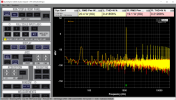
I've been enjoying my AU-555 for a while now. Recently got a QA-403 audio analyzer and still trying to figure out how to use it well but I'll post some test results. It's likely better than shown here since I haven't really optimized my test setup yet but still meets the specs. This is THD+N at rated power. The harmonics go up pretty fast above this level. I've got a lot of 60Hz getting into the test setup and the actual numbers should be better when I can fix that. Still not too bad.
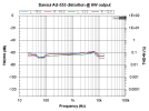
I did a THD+N analysis run over the freq range too at about 3 and 6W output. Distortion is quite a bit lower than full power and pretty good I think.
Here's a plot of frequency response using an aux input at about 4 and 10 watts output. I guess this is the warm Sansui sound?

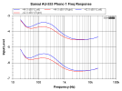
And here the Phono 1 input frequency response. I'm measuring it at the tape record jacks, not at the speaker outputs. I'm getting some feedback or something with phono input and speaker outputs when I turn the volume up so need to get that solved. I have some ideas to try but need some stuff to do it. I think this will look a little flatter if it's going through the amp.
I did a THD+N analysis run over the freq range too at about 3 and 6W output. Distortion is quite a bit lower than full power and pretty good I think.
Here's a plot of frequency response using an aux input at about 4 and 10 watts output. I guess this is the warm Sansui sound?
And here the Phono 1 input frequency response. I'm measuring it at the tape record jacks, not at the speaker outputs. I'm getting some feedback or something with phono input and speaker outputs when I turn the volume up so need to get that solved. I have some ideas to try but need some stuff to do it. I think this will look a little flatter if it's going through the amp.
I had a similar issue with a 555 and the silver mica's were causing noiseTo follow up on @fromnowon's post, the C816 Miller capacitor is a 100pF silver mica type and after many decades of use, may be the susceptible to "silver mica disease".