• The move to the new server is done. There are some software and database maintenance updates in process. This has us passing the hat around to help out. We appreciate any donations. Seriously, even a dollar helps. The payment page may be found here - https://www.audiokarma.org/support.html

Brian's AU-555 restoration

That was quick! Hopefully someone smarter will weight in :)
I see you replaced C814 with WIMA, so we can rule that one out.
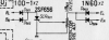
Did you check the protection circuit (BL to EL)? Maybe the germanium diode D903/D904?


upload_2023-5-1_21-44-41.png
 
That was quick! Hopefully someone smarter will weight in :)
I see you replaced C814 with WIMA, so we can rule that one out.
Did you check the protection circuit (BL to EL)? Maybe the germanium diode D903/D904?

I had the same voltage imbalance before recapping too so I don't think it's capacitor related. I've still got a few resistors to replace but I've replaced the ones that were farthest off and it hasn't made any difference so I'm starting to think it's not them either. I haven't even looked at the protection circuit since it wasn't causing me any issues but I'll check it out. Starting to think maybe it's the transistors since some of the other semiconductors on the main amp board have been showing signs of age but I don't know. Strange that the known troublemakers, the 2SC458's, seemed fine but they weren't on the main amp board.

Maybe I should just be happy that it sounds good right now. :)
 
Last edited:
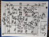
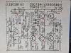
This project has been very educational. I just read a little on crowbar protection circuits using a thyristor but still not that sure if I understand it all so here's how mine looks. There's the voltage imbalance between BL and BR but D901 and 902 seem to be handling that like you'd expect them to. D901 is letting about 44 volts through from BL. D902 is blocking the 44 volts from getting through to BR, which is at about 42 volts. Those are with the volume down. If I turn it up with music playing, the voltages on both sides drop at what seems like about the same rate so BR stays lower than BL by the same 2 or so volts. The gate of SCR901 is clamped to ground potential with the volume all the way down. If I turn the volume up with music playing, the voltage goes up a bit. I saw about 30mV max but not turned up quite all the way so it could probably go a bit higher. I've done full power tests with 1KHz tone and dummy loads and not blown fuses so I'm assuming it's all working the way it's supposed to.

I'm tempted to pull TR805 and 806 just to test them as well as I can. I don't think I have good replacements for them if they're bad though. KSC1815's seem like they might work and I have a few left, but they don't seem ideal (60V vs 70V for the current parts) and I don't have the complements to them on hand either. If anyone thinks the transistors are the best suspects at this point, I'll order some replacements before I pull them I think.
 
Probably DC voltages are closer between channels after adjusting VR801 and VR802 for max unclipped output, as per the service manual.
I have done the service manual alignment. Before recapping, the left channel aligned pretty well but I wasn't able to get the top of the sine wave to clip at all on the right channel. After recapping, I was able to get the top and bottom clipping equally on the right channel but there's still about 3 fewer watts of output on the right channel, and about 5 volts less DC on the right channel.
 
ok, have you considered to see if there is a difference for clipping having a dummy load connected and the same for having it not connected?

Since I am thinking about the base current (for tr806) you will need to provide the current into the load. If the driver transistor (on positive side) and the output transistor would both have quite low HFE, one can have a problem converting the few milliamps of base current of a driver transistor into the two amps or so peak the output transistor has to deliver into the load.
(just thinking out loud...)
 
Last edited:
ok, have you considered to see if there is a difference for clipping having a dummy load connected and the same for having it not connected?

Since I am thinking about the base current (for tr806) you will need to provide the current into the load. If the driver transistor (on positive side) and the output transistor would both have quite low HFE, one can have a problem converting the few milliamps of base current of a driver transistor into the two amps or so peak the output transistor has to deliver into the load.
(just thinking out loud...)
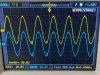
I hadn't considered checking it without a dummy load. I've only done it with them connected. The DC difference exists with the volume all the way down and idle current set at 23mA too if that helps?
 
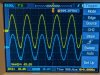
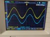
I didn't have a lot of time this evening to mess with it but I decided to try something different to see if I could approach this another way. I hooked the dummy loads and scope up to it and tried playing around with the AC balance pots. I can actually get the channels DC balanced by messing with those but when I do that, I have clipping at the bottom of the sine wave on the right channel even at a pretty low volume level. When I try to set the balance for max output without clipping, the DC gets out of balance and I noticed I'm still getting some glitchy distortion at the bottom of some of the sine waves on the right channel if I turn it up above about 16 watts output. So I guess it's not actually putting out its rated power with a clean signal.

I think I have a new idea to try to find the issue now though. Just didn't have time to mess with it anymore tonight. I'm going to try following the signal through the main amp and see if I can find where that distortion at the bottom of the sine wave on the right channel starts. i guess that should be where my problem is. Hopefully that works. I'm learning a lot working on this thing.
 
I think I have an answer but I'm wrong a lot so if anyone thinks I'm misinterpreting, please chime in. In the pic below, I've got Ch1 on the collector of TR804 and Ch2 on the right channel speaker output. Looks like this is where the issue starts. There is a difference though and I'm not sure how to describe it. The glitch is sort of inverted from the way it looks at the speaker output. I think you can see what I'm saying on the picture. On the emitter of TR808, the glitch looks the same. So the first place I see an issue is at TR804.
PXL_20230503_133605303.jpg

Here's what makes me not so sure it's TR804 though. This pic is the emitter of TR806. It looks closer to what I see at the speaker output.PXL_20230503_143849635.jpg
 
Last edited:
I did a little looking for suggested replacement transistors and I'm not sure I see anything better than KSA1015 / KSC1815 that's actually available. They look like they'd work to me but they also don't quite meet the specs of the original parts. Any suggestions appreciated.
 
The AU-555 service manual lists 2SC734 (O,Y) or CDC8002-1 for TR806; KSC2383 was a suitable replacement for the latter in a AU-555A restoration.
 
The AU-555 service manual lists 2SC734 (O,Y) or CDC8002-1 for TR806; KSC2383 was a suitable replacement for the latter in a AU-555A restoration.
I was not thinking big enough for substitutes I guess. Thank you for the help there. Before I order those and a couple of their complements, I might swap the finals, left channel ones to the right channel and vice versa, just because that's easy to do and will help me rule them out.
 
I swapped the output transistors around and the issue is still on the right channel so at least I know I don't need to buy those. I also changed some more resistors. It's taking a while since I'm doing them one pair at a time and then testing to see if it had any effect. I'd like to know what fixes it if that happens but it would be faster to just do it all at once. I have found 5 or 6 resistors that were outside their 10% tolerance. Still a few pairs that looked a little questionable when checked in-circuit but the ones that looked worst have been changed so unless one of them is noisy, I'm not sure resistors are going to be the issue. I also changed the AC Balance 200K trimmers. The original ones tested a little off in circuit so I pulled them to check and they both only went to 160K so new ones went in. I'll go ahead and finish changing the resistors I have to see if maybe that fixes it. If if doesn't I'll order some new KSC2383's and KSA1013's. Those old TO-92 transistors will be the only thing left to be bad I think.
 
Replaced the last of the suspect resistors and it's still there so just ordered some transistors. I tried zooming in a little farther on the scope and noticed something I hadn't noticed yet. Looks like there's some noise on the left channel at the bottom of the sine wave too. Ch1 is left speaker output and Ch2 is right. I double checked the signal coming into the main amp board and don't see any of that noise there so I think it's all coming from the main amp board. Hopefully by end of next week I'll have new transistors in it.
PXL_20230505_192527929.jpg

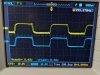
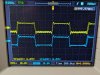
I tried running a square wave through it to see how that looked. I hadn't tried that before. It doesn't seem great to me but I don't have much experience doing this. These are left and right speaker outputs again. I played around with the tone controls, loudness, high/low filters, and they all seem to be working ok. I'll see how new transistors in the main amp board affect this and if it still looks a little rough, I haven't replaced the mylar and mica caps on anything behind the front panel yet.
PXL_20230505_192712402.jpg
 
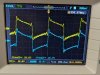
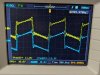
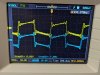
Just thought I'd post some more pics of how the square waves look when I play around with the controls. If anyone with experience interpreting these has any thoughts on them, please let me know what you think. I figured out a lot of the issues with the square wave are because I'm using my laptop as a signal generator. It doesn't put out very clean square waves and the 555 is actually reproducing them pretty faithfully. Hopefully I didn't mix up the pictures & control settings. I think I forgot to take a pic with the low filter on. It did have an effect so I think it's working like it's supposed to.

You can see some extra noise at the bottom of the waveform on the left channel. Now I wish I'd done this test before swapping the output transistors.

This is with the high filter on. It seems to clean it up a bit. Is this what people mean about the mylar caps having a harsh high end? I'll wait until the new transistors are in to see if they clean anything up and then maybe I'll replace the mylar caps so I can see before / after. There's some jitter in this pic but that may be from the soundcard.
PXL_20230505_192724229.jpg

This is with treble tone controls all the way down.
PXL_20230505_192742724.jpg

Treble tone controls all the way up. Yikes. Is that supposed to look like that?
PXL_20230505_192805964.jpg

Bass tone controls all the way down.
PXL_20230505_192817587.jpg

Bass tone controls all the way up
PXL_20230505_192825957.jpg

Loudness on
PXL_20230505_192845837.jpg

I was able to do a sine wave sweep from 10 to 20000 Hz but it's hard to post a pic of that. Looks like it starts coming through pretty clear at around 35 Hz. The output level stays pretty consistent all the way up to about 15-16KHz before it starts dropping off. So I guess that's good?
 
Last edited:
Back
Top Bottom