• The move to the new server is done. There are some software and database maintenance updates in process. This has us passing the hat around to help out. We appreciate any donations. Seriously, even a dollar helps. The payment page may be found here - https://www.audiokarma.org/support.html

Buzz after recap

Have you tested any of these transistors with a diode checker before replacing? Nothing beats the original transistors.

No, I havent actually removed the tranistors yet..... I guess I should do that to confirm my assumptions. I don not have diode checker, but I can check with it my MM. Q4 looks like its been replaced by one of the PO's its labeled "TA814 y78" could not find anything about this transistor other than its a Toshiba. The voltages off it were good, I was only going to replace it as preventative. Q5 also looks like its been replaced more recently with a 2n647. this one has no voltage on pins 16 and 17. Q1 looks original but no voltage on pins 20 through 23. - see my pin readings below from earlier in the thread.

I am a new to vintage stereo repair, although enjoying it greatly. Its like a puzzle. I would love to hear why the older transistors are better. Thanks.
I will remove and check Q1, Q5 and Q6 to check later when I have some time and post results.

Here is why I assume its these transistors.
(AWR 156)
Pin 20: Supposed to be +33v, I have -1.4v
Pin 22: Supposed to be +50v, I have -1.6v
Pin23: Supposed to be +23v, I have -.7v
If I am reading the schem correctly, the Q1 Transistor feeds these pins.
I measured the Q1 Transistor and I have +65V coming in which is correct but then I'm supposed to have 50 v coming of the one leg that feeds pin 22 and 60v out on the other leg which is 10v high.

Pin16: Supposed to be +13v, I have -.3v
Pin17: Supposed to be 7.5v, I have -.3v
Q5 coming in has 24v and its supposed to have 13.5v. Coming out both legs Q5 has 0

So I am thinking both Q1 and Q5 are bad, I also think Q6 is bad as well.
 
Last edited:
Pins 20 and 23 will never be right until Pin 20 is right, as both depend on it.
What is the dcv on the cathode of D8, should be about +14vdc.
Q5 collector (input) should have (almost) +24vdc on it. Its output (emitter) voltage also depends on D8's voltage.
Pins 16 and 17 depend on Q5, so it all goes back to D8, which is where to start troubleshooting your voltage regulators.
 
Pins 20 and 23 will never be right until Pin 20 is right, as both depend on it.
What is the dcv on the cathode of D8, should be about +14vdc.
Q5 collector (input) should have (almost) +24vdc on it. Its output (emitter) voltage also depends on D8's voltage.
Pins 16 and 17 depend on Q5, so it all goes back to D8, which is where to start troubleshooting your voltage regulators.

You nailed Merlynski! Ive got 13.5 on the anode but nothing on the cathode. I actually ordered a few Zener 1N5243B's to replace as a preventative. My transistors and diodes should be here Friday. I'll start with D9! If thats all that is bad. What is your opinion on replacing the transistors as preventative. It has been mentioned that the original are the best. Being a rookie, I am not sure what to do. Leaning towards replacement. Although I understand that mindset of "original".
 
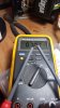
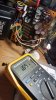
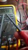
So this is what I get with the - on the cathode.
I get OL when I have + on the cathode.

This means its a good diode....right? Or is it reverse bias? Sorry, still learning....

20200527_195202.jpg .
 
Last edited:
No, I havent actually removed the tranistors yet..... I guess I should do that to confirm my assumptions. I don not have diode checker, but I can check with it my MM. Q4 looks like its been replaced by one of the PO's its labeled "TA814 y78" could not find anything about this transistor other than its a Toshiba. The voltages off it were good, I was only going to replace it as preventative. Q5 also looks like its been replaced more recently with a 2n647. this one has no voltage on pins 16 and 17. Q1 looks original but no voltage on pins 20 through 23. - see my pin readings below from earlier in the thread.

I am a new to vintage stereo repair, although enjoying it greatly. Its like a puzzle. I would love to hear why the older transistors are better. Thanks.
The older transistors are the ones that, At the Time, were the Correct ones that the engineers that designed it called for. Testing and putting it back in rather than shot gunning hand fulls of subs leaves you less vulnerable to never getting that thing working again. If your sub isn't the correct one for example, and you push forward and say put a couple wrong ones in there you have now complicated the repair process and don't even know it yet. Now with that in mind, I have seen a transistor test good on a diode checker and still fail but typically not the case.
There are most definitely better transistors made today but it's best to get it working properly First, Then you can do some preventative updating.
 
Shorted just like I expected. Make sure you replace all the related transistors at the same time, as it is usually a cascaded failure (Q1, Q2, Q5, Q6) and they may be weakened and will fail soon.
EDIT: I misread your meter I thought it showed 0.050, the bar is missing in the 6 on my picture view. UMMM Did the picture change? :confused:
You nailed Merlynski! Ive got 13.5 on the anode but nothing on the cathode. I actually ordered a few Zener 1N5243B's to replace as a preventative. My transistors and diodes should be here Friday. I'll start with D9! If thats all that is bad. What is your opinion on replacing the transistors as preventative. It has been mentioned that the original are the best. Being a rookie, I am not sure what to do. Leaning towards replacement. Although I understand that mindset of "original".
I actually see a typo, I meant D8, -13.8vdc is correct for the anode of D9, it is the reference for the negative regulators.
 
Last edited:
Shorted just like I expected. Make sure you replace all the related transistors at the same time, as it is usually a cascaded failure (Q1, Q2, Q5, Q6) and they may be weakened and will fail soon.

I actually see a typo, I meant D8, -13.8vdc is correct for the anode of D9, it is the reference for the negative regulators.

Gotcha. Going to put D9 back in and test D8. :)
 
1.8 v on the cathode and -0.000 on the anode. Although it is hard to make out the cathode marking on the diode... didnt see the cathode bar..had to look at the schematic which is underside of board.... lol. Now its getting fun! :) Seriously, this is fun.
Also the pic with the diode out and testing is orientatead as it is on the board in the other pic.
20200527_203933.jpg 20200527_203038.jpg
 

Attachments

  • 20200527_204411.jpg
    20200527_204411.jpg
    88.4 KB · Views: 4
Last edited:
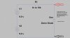
A diode test range on a meter cannot test the zener voltage because it does not have enough voltage drive, it just shows OL Here is a simple circuit to test zener voltage:

ZenerTest3.jpg

You can use a dc supply if you have one, instead of batteries.
 
Yes I agree 300%. I have visited that list a number of times. My point is testing prior to replacement, too many subs in a shotgun approach has its dis-advantages.
I quite agree, the shotgun technique, except under specific circumstances, is not a good repair method.
 
I appreciate the advice. I need to order a tester. In the mean time. I removed Q1 and tested it with my fluke 87 on diode mode. No readings whatsoever. At this point. I;m going to replace the Q1 transistor tomorrow when I get my parts and go from there. Q5 seems good. Removed it and I've got the +lead on the base, the emitter and collector both measured .5

Are my plans good?
 
Last edited:
The caveat with the diode test on a meter is that it can identify bad transistors, but cannot guarantee good transistors. If the meter says it is bad, it is. Transistors fail under real world conditions of voltage and current that the meter cannot test.
Small signal cheap transistors I just replace if I suspect a problem, even if the diode test shows good junctions.

Plans look good to me.
 
Thanks. That makes sense. I am looking forward to moving on to the next boards after this one is fixed. I can see how if you just jump in and replace everything all at once, troubleshooting would be significantly more difficult.
 
If you installed larger capacitance in the main power supply the current surge may damage the rectifying diodes that feed them. This failure may occur after testing your amplifier and giving it some use without any apparent buzz untill next time you turn it on and the surge damages the diode. A bad rectifying diode may give confusing voltage readings and may even explain the buzz as well as what you saw in the dim bulb tester. If you have not done it yet, it may be worthwhile inspecting all of the rectifying diodes for leakage or shorted junction. Also, in my opinion, the polyester capacitors bypassing the main electrolytic capacitors should have their leads as short as possible because they are parasitic inductors. The leads shown seem too long.
Good luck!!
 
Back
Top Bottom