• The move to the new server is done. There are some software and database maintenance updates in process. This has us passing the hat around to help out. We appreciate any donations. Seriously, even a dollar helps. The payment page may be found here - https://www.audiokarma.org/support.html

Buzz after recap

If you installed larger capacitance in the main power supply the current surge may damage the rectifying diodes that feed them. This failure may occur after testing your amplifier and giving it some use without any apparent buzz untill next time you turn it on and the surge damages the diode. A bad rectifying diode may give confusing voltage readings and may even explain the buzz as well as what you saw in the dim bulb tester. If you have not done it yet, it may be worthwhile inspecting all of the rectifying diodes for leakage or shorted junction. Also, in my opinion, the polyester capacitors bypassing the main electrolytic capacitors should have their leads as short as possible because they are parasitic inductors. The leads shown seem too long.
Good luck!!

That's interesting. I kept the main filter caps stock with 18000uf 75v. However on the power supply board, it had two 100uf 80v in c11 and c12 spot. They were original to the board. The schematics show that c11 and c12 are 220uf 80v. So I replaced them with 220uf 100v. I do have a couple 100uf 100v if I need them though. Anyway, other than that, the only thing I did different was add the bypass caps. I will take your advice and shorten them. I will check the rectifier diodes. I have a bunch of diodes coming tomorrow.... 400v 3 amp as well as a selection of lower voltage.

Thanks
 
I was looking at the cheepos...any difference? I'm always open to save a buck. :)
Good tools are worth the investment. At the time I bought the cheapo it was all I could justify. It has cheap leads, no case, display flops. I need to build a case. Sometimes it gives me a really whacked out reading, I have to disconnect and power cycle to recover. If you can afford the DCA55 I would do it. I want the DCA75, at twice the price, but actually does curve tracing.
 
Thanks. What started as a desire to rebuild my SX980 may have turned into a hobby....I think I may start acquiring some tools like this. I have already purchased some stuff including a really cool solder sucker from Digi (engineer ss02)...
 
Replaced rectifier diodes, zener D8, Q1, Q5 and Q4. Double checked everything else.
Started her up on DBT with no load. Relay clicked in 6 seconds. function lights on.
Adjusted Bias and voltage with DBT on.
Took it off DBT and redid "tail of the dragon".
Shut her down, hooked up some old fishers I have: No buz or hum!
Sounds great. Went through the functions.
When I switch it to Mono. My right channel drops out and and no right meter response.
Switch it back to stereo and alls good.
Hmmmmm.....

Any ideas?
 
Look for solder bridges (or clipped leads fallen across) at the switch.
Deoxit and multiply repeated exercise, deoxit and multiply repeated exercise, etc. on the Stereo/Mono switch.
 
Look for solder bridges (or clipped leads fallen across) at the switch.
Deoxit and multiply repeated exercise, deoxit and multiply repeated exercise, etc. on the Stereo/Mono switch.
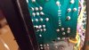
Nice call Merlynski! Exactly what it was. Solder bridge underneath. Heat and solder suck fixed it. Funny thing is, it must have been like that all this time. Never had it in Mono before. Was just going through the switches post fix.
You clearly know your stuff! I really appreciate you and everyone else here a the forum who has helped me out. I feel I have learned a lot so far.
I set up a little work station near a window in the basement to finish this project. Then I have a feeling I will be popping in the thrifty stores more often looking for something to tinker with.
Heres a pic of that solder bridge.
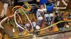
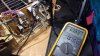
So I will close this post with a few pics. If I run into any other problems. I will start a new one.
Thanks again.
20200529_224208.jpg 20200529_225459.jpg
Will wrap the wires after all the other boards are done.
20200529_202627.jpg
 
Last edited:
You're welcome and
Congratulations on a successful repair.
That looks like an original wave solder bridge. Somebody at the factory missed it.
 
Last edited:
Back
Top Bottom