• The move to the new server is done. There are some software and database maintenance updates in process. This has us passing the hat around to help out. We appreciate any donations. Seriously, even a dollar helps. The payment page may be found here - https://www.audiokarma.org/support.html

Buzz's Acro UL-II Monoblock Project

BuzzK

AK Member
Subscriber
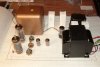
I took my standard chassis and had some monoblock versions made (power and jacks in the back; the rear & front are the shorter sides).

I've been saving a pair of Acrosound TO-600 UL PP 5K trannies; these can take EL34 / KT77 / KT88 output pairs. I also have some other iron I'm recycling from another project.

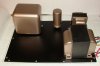
The photo shows initial parts placement -- the outputs won't have caps, and the square boxes represent polypropylene motor caps, etc.

They will be complete mirror images of each other.

Something to keep me busy during these dark winter hours . . .

- Buzz
 

Attachments

  • Mono Layout.jpg
    Mono Layout.jpg
    84.3 KB · Views: 274
Register to hide this ad
Mr. K, I also have one of your chassis (a brute btw) and am going to build an amp on it (I will start another thread).

It has a nice thick aluminum panel for the top. I have many Greenlee chassis punches. Will they suffice?
 
Mr. K, I also have one of your chassis (a brute btw) and am going to build an amp on it (I will start another thread).

It has a nice thick aluminum panel for the top. I have many Greenlee chassis punches. Will they suffice?

Greenlees work great on the aluminum -- that's what I use for standard sizes. Even the Harbor Freight ones will do, but I don't recommend them for steel or long service.

Buzz
 
Hiya,

Will be watching this one for sure. I have a similar project in mind.

Frannie
 
If you have CNC, why not cut it directly?,I thought most wood bits can cut aluminum,I have cut aluminum with my battery powered circular saw.
 
I have considered it and it should do it.

However:
1. It is possible and even likely I will need some kind of lubricant (do not want to have oil all over my wood spoilboard). Compressed air to cool the bit may work but then I've got aluminum "sawdust" everywhere. The router on the CNC machine will not go slow enough for a conventional drill bit. An end mill might work though using a peck-drilling process.

2. I'm gonna cut a wood template on a scrap board anyway just to verify fit-up.

Obviously the best part would be using the endmill in the CNC to cut the tube openings, etc. out. Certainly deserving of future experimenting as others have done this with the same machine I have but they usually use lubricant and have a spindle instead of a wood router than can be controlled to a lower rpm better.
 
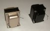
Aesthetics matters, I think. Having a coppery-gold potted transformer standing out against the rest of the other (black) iron would be odd. Trying to match the original coppery color is next to impossible using shelf-bough spray paints (I'm told that paint huffers prefer gold tones, which has created a shortage on the shelves. Who knew).

Anyway, as my son is applying for colleges this year, I think it would be relevant to select black and gold. :-)

Which means I'll have to repaint the old part to match the gold I'm using for the others (cashmere beige metallic, to be precise). I know that lessens the value of a vintage part, but no one can enjoy that part sitting by itself . . .
 

Attachments

  • Chokes sm.jpg
    Chokes sm.jpg
    76.2 KB · Views: 80
Hiya,

Gold and Black .. lets see ..

What University would that be :)

Ramblin Wreck ???

Frannie
 
Never can get anything by you, Frannie . . . :-)

The kid wants to go to Stanford, but I'd have to rob a bank, with another one in college. Plus, his SAT of 2390 makes him just a "run of the mill applicant."

I've told him Ga. Tech is the only college that comes with a brand new car . . . :-)
 
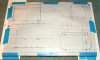
The next step was to lay out the parts on a grid for the drill pattern.

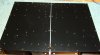
I sandwiched a piece of cardboard between two top plates -- front to front -- and bolted them together (the panels had a tendency to "potato chip" after they were machined by the fabricator). This way, a hole drilled in one panel would create a mirror-imaged hole in the other. The cardboard helps to minimize scratching caused by the drill debris.

I used a small pilot drill (5/64) for the center guides. I started to drill and punch the chassis. I realized that I need a 1.5" Greenlee for the two large poly cap cans, so I found one on eBay.

In the meantime, maybe I'll have a few things silkscreened on the top plate while I wait for the large punch . . .
 

Attachments

  • drawing.jpg
    drawing.jpg
    104.7 KB · Views: 38
  • pilot holes.jpg
    pilot holes.jpg
    90.6 KB · Views: 32
  • mirrored.jpg
    mirrored.jpg
    93.2 KB · Views: 36
  • Starting to punch.jpg
    Starting to punch.jpg
    140.5 KB · Views: 44
I did a bit of math to be sure that the parts I had on hand would work together.

Dave "Guru" Gillespie pointed out that the amp (with KT-88s) wouldn't put out 60W RMS/Ch with a 270 VA power transformer, but there isn't anything in my house that I can hook up to that will take 10W without driving me out the of the room anyway. "Pleasant peaks" will do for now . . .

* * *

Notes on Acrosound II Amplifier Power Supply Redesign


The Acrosound II UL OPT transformers are suitable for EL34 or KT88. I have only one of the power supply transformers, but I have two 1000 VAC Hammond 282X power supply transformers, and two Triad 10H chokes on hand.

I’m hoping to use them in a choke-input power supply design (the original was capacitor input, with a choke filter wound inside of the power supply iron!) I’ve selected two 35 MFD polypropylene capacitors to be used in parallel as filters after the choke. The supply will feed a mono amplifier with two KT-88 tubes running in UL mode, biased approx. 65 mA each with a target plate voltage of 470 VDC.

Parts specs:

Hammond 282X Power XFMR

273VA (115V input)
200mA (secondary)
500-0-500 VAC
5V@3A CT
6.3V@3A CT

Triad Choke
200 mA
150 ohm DCR

Terms & equations:

Vin(RMS) is the voltage before rectification;

Vin(RMS) = 124/115 x 500 VAC = 539 VAC

Choke output voltage = 0.90Vin(RMS) = (539 x 0.9) = 485 VDC

Minimum load current = Imin(mA) ≈ Vin(RMS) / L(H) = (539/10) = 54 mA

Current rating:

120 Hz: iAC(positive peak) = Vin(RMS) / 2772L = 539/27720 = 19.4 mA

i total peak current = IDC + iAC(peak)

= 130 mA (KT88x2) + 19.4 mA = √ 149.4 mA (choke rated @ 200 ma)

Looks like we're good to go. I have to determine circuit values downstream of the 70 MFD capacitance -- I'd like to use small chokes and poly caps for low noise.
 
Last edited:
BZ, that looks good. Just starting to do some punching of my own on a panel like that. Lessons learned:

1. Male portion (with knife edge) of punch goes on top, the female portion goes on the bottom (since it will scratch the panel).
2. Greenlee's are more $$ but worth it.
3. I use an air ratchet to sloowwly turn screw rather than wrench by hand (after thorough lubrication of threads and knife edge).
 
Back
Top Bottom