You are using an out of date browser. It may not display this or other websites correctly.
You should upgrade or use an alternative browser.
You should upgrade or use an alternative browser.
CA-3000 the hunt begins
- Thread starter vigman
- Start date



vigman
SUBSCRIBER
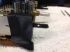
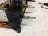
The finished prototype
OK….
The idea was to add the extra bit of lever to save the switch mechanism.
and I LOOKED for a used one with no results..
So took a switch out of a scrap AU-717..
Cut the shaft off.
Used the mounting bits on the face of the shaft to be the splint.
Laid the new shaft against the old one so the final length would be CLOSE.
Looked at the front sub panel to see how far the first screw would have to be
without hitting the sub panel and drilled 1st hole for 4/40 tap.
Cut new shaft a TAD long so I could file to fit ( if the cut wasn't square ).
Drilled a 2nd hole in the new shaft tip for 4/40 tap.
Eyeball, file , measure, file..
Made a splint of some soft copper from an old AC plug.
Nailed it on the first attempt.. fit everything together checked function
Works nice…. Now used the front panel bits to make the final splint..
Transferred the hole marks, drill 4/40 clearance, dry fit looks good.
Clean it all up, use loc tite RED as a thread lock AND a glue..
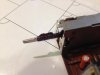
Let it dry.. final filing ( take most of the head off the 4/40 button heads and extra thread off the back, hand file the edges, a little black sharpie.. and BADA BOOM a switch extension ! total cost NADA. Time about 2 hrs.
Now the OH BY THE WAYS.. the sub panel has clearance for about 2 switch levers so I MIGHT have to open that up a few thou. and I'm not sure what mods ( if any ) for the thicker shaft to fit in the bezel…
So there you you have it…..
OK….
The idea was to add the extra bit of lever to save the switch mechanism.
and I LOOKED for a used one with no results..
So took a switch out of a scrap AU-717..
Cut the shaft off.
Used the mounting bits on the face of the shaft to be the splint.
Laid the new shaft against the old one so the final length would be CLOSE.
Looked at the front sub panel to see how far the first screw would have to be
without hitting the sub panel and drilled 1st hole for 4/40 tap.
Cut new shaft a TAD long so I could file to fit ( if the cut wasn't square ).
Drilled a 2nd hole in the new shaft tip for 4/40 tap.
Eyeball, file , measure, file..
Made a splint of some soft copper from an old AC plug.
Nailed it on the first attempt.. fit everything together checked function
Works nice…. Now used the front panel bits to make the final splint..
Transferred the hole marks, drill 4/40 clearance, dry fit looks good.
Clean it all up, use loc tite RED as a thread lock AND a glue..
Let it dry.. final filing ( take most of the head off the 4/40 button heads and extra thread off the back, hand file the edges, a little black sharpie.. and BADA BOOM a switch extension ! total cost NADA. Time about 2 hrs.
Now the OH BY THE WAYS.. the sub panel has clearance for about 2 switch levers so I MIGHT have to open that up a few thou. and I'm not sure what mods ( if any ) for the thicker shaft to fit in the bezel…
So there you you have it…..
Attachments



that's my kind of recycling - nice job
vigman
SUBSCRIBER
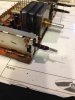
The final fit
Well hind sight is 20/20.
1st 2/56 screws and flat heads would have been better.
I'm removing a fair amount of material to get her to fit PROPERLY.
The total width of the splint is wide... by about a 32nd..
So filing, filing trimming filing.
I'm ALMOST there...
Well hind sight is 20/20.
1st 2/56 screws and flat heads would have been better.
I'm removing a fair amount of material to get her to fit PROPERLY.
The total width of the splint is wide... by about a 32nd..
So filing, filing trimming filing.
I'm ALMOST there...
Attachments


vigman
SUBSCRIBER
All the recapping ( that I feel needs to be done ) is done….
I did the power supply reg boards and the final output (s) ..
I left the main input board alone.. It does a NICE job on square wave, freq response is great X talk is REALLY LOW it's got a cleaner , quieter noise floor than my AU-20K… about 4.5 DB ISH.. The reed relays still work BUT the turn on time is a bit weird
Left…1….2….3 RIGHT that is due to the PS ( or something ) causing a really SLOW ramp to the reed coils and the right channel seems to take MORE gauss to get em to close ( or the left internal reed is weak/ soft )
Critical listening… not much to tell the truth.. either on cans AKG K-240's OR thru my Fisher 400 ( rebuilt ) and JBL L-100's series 2…
ANY pre amp that can spec 8 volt output has my respect But I was only able to get 6.7 volts before it started to soft clip which is about 250% MORE that you would NORMALLY need…
Mine is a " later model " that had all the jumpers in going from top to bottom already there. I really flexed the boards looking for that issue...
There was still a fair amount of cold solder connections..
The BIGGEST issue aside from the ABUSE was all my boards are silver pins & sockets. Unlike other Sansui rigs that are GOLD.. I had a LOT ( well every connector ) needed some scraping, cleaning to get PROPER connection back.. and on first fire up it sounded ….. cheap,, scratchy… like a bad interconnect cable… and there are a TON of connections in there… ground pins & power supply pins were the worse. you got a black oxide on both sides of the connection.. I will venture a guess, that this unit came from back east and it was in a high humidity area ( damp N salty ) … it all cleaned up easy.. it was just a lot of work.. The devices ( transistors ) aren't really fast ) spec wise but hey my SWEET SPOT is older tube gear
I did the power supply reg boards and the final output (s) ..
I left the main input board alone.. It does a NICE job on square wave, freq response is great X talk is REALLY LOW it's got a cleaner , quieter noise floor than my AU-20K… about 4.5 DB ISH.. The reed relays still work BUT the turn on time is a bit weird
Left…1….2….3 RIGHT that is due to the PS ( or something ) causing a really SLOW ramp to the reed coils and the right channel seems to take MORE gauss to get em to close ( or the left internal reed is weak/ soft )
Critical listening… not much to tell the truth.. either on cans AKG K-240's OR thru my Fisher 400 ( rebuilt ) and JBL L-100's series 2…
ANY pre amp that can spec 8 volt output has my respect But I was only able to get 6.7 volts before it started to soft clip which is about 250% MORE that you would NORMALLY need…
Mine is a " later model " that had all the jumpers in going from top to bottom already there. I really flexed the boards looking for that issue...
There was still a fair amount of cold solder connections..
The BIGGEST issue aside from the ABUSE was all my boards are silver pins & sockets. Unlike other Sansui rigs that are GOLD.. I had a LOT ( well every connector ) needed some scraping, cleaning to get PROPER connection back.. and on first fire up it sounded ….. cheap,, scratchy… like a bad interconnect cable… and there are a TON of connections in there… ground pins & power supply pins were the worse. you got a black oxide on both sides of the connection.. I will venture a guess, that this unit came from back east and it was in a high humidity area ( damp N salty ) … it all cleaned up easy.. it was just a lot of work.. The devices ( transistors ) aren't really fast ) spec wise but hey my SWEET SPOT is older tube gear
vigman
SUBSCRIBER
More switch bodges here
http://www.audiokarma.org/forums/showthread.php?t=599944
http://www.audiokarma.org/forums/showthread.php?t=599944
vigman
SUBSCRIBER
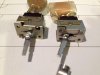
Switch bodge ALA 2/56 version
Saved TWO of the Big power switches so this takes care of the Japan BA 3-K and the US-BA-3K. Cost 3 dollars for 2/56 screws and 2 hrs…
MUHAHAHAHAHAHAHAHAH
one switch is a LITTLE more hogged out in the front since the shaft snapped REALLY close to the front of the switch face… Once installed you will NEVER see it…
Better than 130 some odd bucks PER switch IF you can find em…
Saved TWO of the Big power switches so this takes care of the Japan BA 3-K and the US-BA-3K. Cost 3 dollars for 2/56 screws and 2 hrs…
MUHAHAHAHAHAHAHAHAH
one switch is a LITTLE more hogged out in the front since the shaft snapped REALLY close to the front of the switch face… Once installed you will NEVER see it…
Better than 130 some odd bucks PER switch IF you can find em…