• The move to the new server is done. There are some software and database maintenance updates in process. This has us passing the hat around to help out. We appreciate any donations. Seriously, even a dollar helps. The payment page may be found here - https://www.audiokarma.org/support.html

Can anyone please help ID this amp?

yurauki

Member
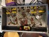
Picked up this beauty as my first-ish restore project in no-power, parts-only condition. pic 3.jpg
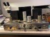
Not being able to find anything similar, I'm leaning towards this being a very nice DIY build, that reminds me of a Dynaco ST70 or some version of Williamson circuit. I have a slim hope of finding a schematic to this as being some sort of kit, or similar, or at least the power tranny specs.

Tube complement: 2x 6AN8, 4xEL37, rectifier tube missing, possibly 5U4?
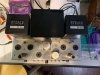
pic 2.jpg
A first visual inspection reveals charred terminals on the power tranny - uh-oh... It has 10 screw terminals and some of them are less than even finger-tight. I am hoping this has led to overheating in the past and not some sort of short. The plan is to take off the screw terminals, dig out the leads, clean them, solder proper pigtails and test the tranny for signs of life. If the tranny lives, yay me. If not I have a choice of a few beefy replacements on hand, or will look for replacements, but will need help approximating the specs. An out of place Philco transformer doing what I think is power supply for the bias duty, suggests that either the power tranny has been through a lot, or if it did not come with a bias tap originally lends support to the DIY project idea. pic 1.jpg

That's about as far as I got. Thanks in advance!
 

Attachments

  • pic 1.jpg
    pic 1.jpg
    160.9 KB · Views: 45
  • pic 2.jpg
    pic 2.jpg
    117.1 KB · Views: 44
  • pic 3.jpg
    pic 3.jpg
    115.3 KB · Views: 44
  • pic 4.jpg
    pic 4.jpg
    86.3 KB · Views: 43
Register to hide this ad
With the 6AN8 it's a Dynaco-style circuit. Those 420's are very nice, 6.6K p-p, so yeah, EL37s, EL34s or 6L6 or KT66s. Even if the PT is bad, you've got some great components there. Should be well worth rebuilding.
 
That small transformer may be a choke. The A-420 would typically have been used with cathode bias. The coupling caps don't correspond with the standard Dynaco 6AN8 front end in the catalog, so it looks like whoever built it did his own thing. Looks professional, though. I'd reverse-engineer the circuit and take special not of the values for any low-pass filters on the front end, and the feedback values, since those would be customized for the "hybrid" build.
 
Thank you all for your time and replies!

Gadget73:Thank you! that’s the first schematic I saw and the basis for my guess as to rectifier tube being a 5u4. But the first schematic - the Dynakit the power tranny has 11 taps, mine has 10. The second A430- the improved Williamson has 10 taps but the topology is for triode drivers 6sn7. So maybe a combination of the two.

Zackthedog: Thank you! That’s what I’ve been thinking. The outputs and that chromed chassis look sharp. I didn’t roll the dice on the EL37s given the price, the crispy tranny and no way to test at the time, but I do have a bunch of 6L6GCs and a bunch of 7027As on hand to play with.

That was my first guess on the Philco as well, but it has 5 leads, two of which go to that orange selenium rectifier and two go to the taps on the power tranny. I was hoping to not have to trace the spaghetti, as I’m not too good at that, but looks like I’ll have to do just that after all.

Dave: Thank you! Is the catalog the same one as what Gadget linked to or is there another one floating out there?
 
Welcome to audiokarma..Heres the transformer catolog @dcgillespie is talking about.
http://knob.planet.ee/kirjandus/books/Dynaco_Transformers.pdf
Fwiw that layout looks very familar to my eyes and might of been built from a aritcle in a magazine called audio from the 50's.There were lots of articles on building diy amps and yours is probally one of the many published.
You can check here and check out the magazine and possibly find the exact amp.
https://worldradiohistory.com/Archi...ng,highlighted consumer electronics and music.
 
Thank you all for your time and replies!

Gadget73:Thank you! that’s the first schematic I saw and the basis for my guess as to rectifier tube being a 5u4. But the first schematic - the Dynakit the power tranny has 11 taps, mine has 10. The second A430- the improved Williamson has 10 taps but the topology is for triode drivers 6sn7. So maybe a combination of the two.

Zackthedog: Thank you! That’s what I’ve been thinking. The outputs and that chromed chassis look sharp. I didn’t roll the dice on the EL37s given the price, the crispy tranny and no way to test at the time, but I do have a bunch of 6L6GCs and a bunch of 7027As on hand to play with.

That was my first guess on the Philco as well, but it has 5 leads, two of which go to that orange selenium rectifier and two go to the taps on the power tranny. I was hoping to not have to trace the spaghetti, as I’m not too good at that, but looks like I’ll have to do just that after all.

Dave: Thank you! Is the catalog the same one as what Gadget linked to or is there another one floating out there?

Oh, so fixed bias! Interesting mish-mash of Dynaco circuits. ;-) Anway, it'll be a great project!
 
Radioactive: Thank you! So glad to be here. Love worldradiohistory website! My problem is when I start looking for my amp, I end up wondering what's the deal with that half of the 6SN7 in the power supply on page 30 of the February 1954, before I can even get to March! ;) I guess I really need to get my act together.

Zack: =)

Anyhoo, great meeting everyone! Thank you for all the responses and wisdom. I will be back for the sanity check with my spaghetti tracing schematic.
 
yeah that site can be something of an attention trap. Some really interesting circuits. Shame its not practical to build a bunch of those various less-common designs just to see how they actually perform.
 
Updates: tested the power tranny, with a light bulb limited variac. Windings as follows: Pri: 0-120VAC, Sec: HV 320-0-320; Fil: 6.07-0-6.07; 5v fil: 0-5.72;
So good news, it's alive! Mixed news, what's up with the voltage on the filament line? I was expecting it to be a bit higher unloaded... And seeing how the burnt wires were on the filament winding maybe part of that winding is shorted? But one side of the filament winding to center tap has the same voltage as the other side of the winding to center tap, if part of that were shorted, would it still be symmetrical?

Diagram to follow....
 
Is it really 6.07-0-6.07? That would be a 12 volt filament tap, which seems odd. If the small Philco tranny is for the negative bias voltage and is a reversed filament tranny (which would be typical), and the secondary is tied the main tranny filament taps, then those taps are seeing a load, though a very small one. But that still seems odd.

It looks like there's plenty of room to add an extra filament tranny underneath if you need to.

Do you get a negative voltage from the bias rectifiers?
 
not impossible, I have a big power trafo out of an organ that is a 6-0-6 for the filament winding. It was a mix of 6 and 12v tubes. 12v ran end to end, the 6v all ran from ground to one end or the other.
 
I goofed up. I will be doing a lot of that - sorry! Upon further reflection I noticed that all the voltages read low - at least in a sort of similar williamson design the voltage after the second filter appears to be 450-470VDC? If I am reading the tube data for the 5U4GB correctly I could get that kind of voltage if I have 450VAC on each plate for an output of 460VDC @ 275mA. So I measured it at the input of my variac and sure enough, using the 40W bulb to limit the current sagged my supply down to about 100VAC, (when it should have been closer to 120VAC) hence the low voltages across the board. I upped it to a 150w bulb and used the boost tap to get more headroom from my variac. At the actual 117VAC supply I now get HV Sec: 356.9-0-356.9 Fil.: 6.77-0-6.75 5v Fil.: 5.659VAC. Now, I'm nowhere near 450VAC per plate (at 125-127VAC I get about 380-0-380), but those filament voltages look fine now to me.
 
I goofed up. I will be doing a lot of that - sorry! Upon further reflection I noticed that all the voltages read low - at least in a sort of similar williamson design the voltage after the second filter appears to be 450-470VDC? If I am reading the tube data for the 5U4GB correctly I could get that kind of voltage if I have 450VAC on each plate for an output of 460VDC @ 275mA. So I measured it at the input of my variac and sure enough, using the 40W bulb to limit the current sagged my supply down to about 100VAC, (when it should have been closer to 120VAC) hence the low voltages across the board. I upped it to a 150w bulb and used the boost tap to get more headroom from my variac. At the actual 117VAC supply I now get HV Sec: 356.9-0-356.9 Fil.: 6.77-0-6.75 5v Fil.: 5.659VAC. Now, I'm nowhere near 450VAC per plate (at 125-127VAC I get about 380-0-380), but those filament voltages look fine now to me.

Oh gosh, no problem! :-) I'm guessing the rectifier was a 5AR4, giving you around 450VDC.
 
Is it really 6.07-0-6.07? That would be a 12 volt filament tap, which seems odd. If the small Philco tranny is for the negative bias voltage and is a reversed filament tranny (which would be typical), and the secondary is tied the main tranny filament taps, then those taps are seeing a load, though a very small one. But that still seems odd.

It looks like there's plenty of room to add an extra filament tranny underneath if you need to.

Do you get a negative voltage from the bias rectifiers?

The little Philco tranny is a 32-8502 - looked all over, but could not find the specs for that part number. Was able to find out that based on Philco numbering system it is either a power or an output transformer.

I could not test the negative bias rectifier as I had to pull the power tranny. Previous owner said he had it tested and there was "some weird short." After pulling the tranny and unscrewing all the screw terminals and that brown looking board with charred spots and screw terminals some of which burned large holes in that board, some were not even tight and all very dirty. Also found some large lose blobs of solder rolling around in there, so that could have caused a short to the case as some wires had most of the insulation stripped. Since there is just enough wire left sticking out, the plan is to ditch the screw terminals, clean up the remaining wires well, solder on some properly colored pigtails, insulate well and secure in place.
 
Oh gosh, no problem! :) I'm guessing the rectifier was a 5AR4, giving you around 450VDC.
Wouldn't you still need over 400VAC per plate for that? (per https://www.drtube.com/datasheets/5ar4-amperex1958.pdf);
I guess it is possible at 360VAC per plate if you are drawing 175mA or so. Now you actually may be right about the 5AR4, which also has a maximum capacity for a condenser input filter at 60uf, versus 5U4, at 40uf. The first filter cap, as well as the other 2 are 40uf at 450v. Hmm, but then that voltage rating on the caps suggests maybe a lower design working voltage?
 
Last edited:
Wouldn't you still need over 400VAC per plate for that? (per https://www.drtube.com/datasheets/5ar4-amperex1958.pdf);
I guess it is possible at 360VAC per plate if you are drawing 175mA or so. Now you actually may be right about the 5AR4, which also has a maximum capacity for a condenser input filter at 60uf, versus 5U4, at 40uf. The first filter cap, as well as the other 3 are 40uf at 450v. Hmm, but then that voltage rating on the caps suggests maybe a lower design working voltage?

You know, it's hard to say with a mish-mash DIY amp like this, but a 5AR4 makes sense given the Dynaco designs of the time. A 5U4 would really drop a lot, like down to 400VDC. You could be right, though. The amp looks to be very well built and the original builder might have pursued his own ideas. Hard to say. But it will be interesting to follow this mystery. ;-)
 
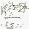
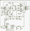
So far my schematic is this:
My amp.png

This is not a final version as I need to update the resistor going to pin 7 of 6AN8 as 1.5M and to pin 6 as 27K, add some resistors to the input and get rid of one of the filter caps, as there are only 3 in the supply filter. And I'm sure some other things I missed, but just wanted to make sure it makes sense so far. Do I have that diode in the negative bias supply facing the right way? (The negative everything-backwards thing trips me up)

Also, in the process of tracing wires, I think there are 4 x 35mm jacks on each of those cathode connections to ground - I'm guessing a fancy way to measure the cathode current for each output tube? One of them seems to have no actual connection to the ground. That seems like a bad thing for one side of a push-pull, no?
 

Attachments

  • Original.png
    Original.png
    496.1 KB · Views: 15
Back
Top Bottom