

You are using an out of date browser. It may not display this or other websites correctly.
You should upgrade or use an alternative browser.
You should upgrade or use an alternative browser.

So far my schematic is this:
View attachment 2637197
This is not a final version as I need to update the resistor going to pin 7 of 6AN8 as 1.5M and to pin 6 as 27K, add some resistors to the input and get rid of one of the filter caps, as there are only 3 in the supply filter. And I'm sure some other things I missed, but just wanted to make sure it makes sense so far. Do I have that diode in the negative bias supply facing the right way? (The negative everything-backwards thing trips me up)
Also, in the process of tracing wires, I think there are 4 x 35mm jacks on each of those cathode connections to ground - I'm guessing a fancy way to measure the cathode current for each output tube? One of them seems to have no actual connection to the ground. That seems like a bad thing for one side of a push-pull, no?
Great job so far! Comments:
1) Yes, I think you have the diode backwards. ;-)
2) That feedback resistor seems very low in value, like by a factor of 10. Maybe 1800?
3) Resistor to pin 6 of the 6AN8 should be 270K, not 27K. That's way to low a load for the pentode, I think. Check again?
4) Looks like he took some shortcuts in the PS, eliminating the choke filter. Shouldn't be a problem, I suppose.
5) The jacks would have been a way to insert an ammeter in the cathode circuit to balance the output tubes. They would normally be a closed connection. Certainly would be worth checking to make sure all cathodes are grounded with the jacks in normal (closed) position. Ideally, you'd want to insert a 10 ohm resistor between each cathode and ground to measure the bias current of each tube individually. Repurpose the test jacks to measure DC volts across each resistor to ground for biasing.
Last edited:
Skiz shows Mullard 5/20 topology, not Williamson.
Well, no, it's a "Dynaco" circuit, pentode voltage amp to triode cathodyne phase splitter. Mullard would be pentode voltage amp to long-tailed pair phase splitter.

Pio1980
AK Member
Right, Laurent topology.Well, no, it's a "Dynaco" circuit, pentode voltage amp to triode cathodyne phase splitter. Mullard would be pentode voltage amp to long-tailed pair phase splitter.
Got crossed up.
Right, Laurent topology.
Got crossed up.
Oh, that's what it's called! Thanks, I didn't know that.
Pio1980
AK Member
Brilliantly elegant simple P/P driver ckt using bog-common small-signal triode/pentode television tubes.Oh, that's what it's called! Thanks, I didn't know that.
Some amps use similar ckt with 12AX7 dual triode.
Great job so far! Comments:
1) Yes, I think you have the diode backwards. ;-)
2) That feedback resistor seems very low in value, like by a factor of 10. Maybe 1800?
3) Resistor to pin 6 of the 6AN8 should be 270K, not 27K. That's way to low a load for the pentode, I think. Check again?
4) Looks like he took some shortcuts in the PS, eliminating the choke filter. Shouldn't be a problem, I suppose.
5) The jacks would have been a way to insert an ammeter in the cathode circuit to balance the output tubes. They would normally be a closed connection. Certainly would be worth checking to make sure all cathodes are grounded with the jacks in normal (closed) position. Ideally, you'd want to insert a 10 ohm resistor between each cathode and ground to measure the bias current of each tube individually. Repurpose the test jacks to measure DC volts across each resistor to ground for biasing.
1) I knew it!
2) Brown-grey-brown-silver, that's 180ohms 10%? (check the third pic in my first post - that's the big resistor next to the postage stamp molded caps - btw are those mica or paper?) I'll trace that line again for any other resistance in series that I'm missing. Btw I'm not finding that 680Ohm to the ground either... Does it make a difference that they are lifting the feedback at the 8ohm tap (yellow) instead of 16(orange)? Given the info in #4 below your estimate seems right on the money though, so I'm confused.
3) Red-Purple-yellow-Silver = 2-7-0,000 right you are, 270k 10%
4) So given the similarities, I think this is actually a tweaked Dynakit Mark II circuit featured here: https://worldradiohistory.com/Archive-All-Audio/Archive-Audio/50s/Audio-1956-Sep.pdf#page=58
it does not seem to feature a choke filter supply, just the el-cheapo CRC.
5) I've heard of this mod before and I like the solid direct path to the ground at all times much better than relying on the jack ground leaf to make a perfect connection every time.
Brilliantly elegant simple P/P driver ckt using bog-common small-signal triode/pentode television tubes.
Some amps use similar ckt with 12AX7 dual triode.
Pio, thanks for joining the conversation and for your comments! I will probably be researching and mostly asking a lot of questions about variations of those topologies as they relate to different versions of the 6L6 family. As I mentioned, I opted to not go with the original Mullard EL37's, but I have the 7072A's that I would like to use, or in the alternative the 6L6GC's. I know I may have to do some minor mods at the socket since 7072A's wouldn't like the pins 8 and 1 shorted and the pin 6 used as a free connection lug.
In addition, while I should have some 6AN8's in my stash, I'm also aware of 6EA8/6U8 possible compatibility - which are more plentiful for me.

postage stamp molded caps - btw are those mica or paper?)
probably mica, though that basic style did exist in paper cap. Sometimes you can tell by the dots, but not all of them used the first dot for type and just went straight into the value. Fair bet if its in the feedback circuit or a cap+resistor to ground off the pentode plate its some picofarad value, and most likely mica. If it comes out to be something like 0.01uf, then I'd expect paper but usually those are physically much larger.
The Laurent driver is sometimes considered sort-of a simplified Williamson. I guess because its typically direct coupled like the first tube in a Williamson. Instead of having more gain between the inverter and the output tubes though, it does it all in one stage with a pentode vs using what amounts to two medium gain triodes in series.
probably mica, though that basic style did exist in paper cap. Sometimes you can tell by the dots, but not all of them used the first dot for type and just went straight into the value. Fair bet if its in the feedback circuit or a cap+resistor to ground off the pentode plate its some picofarad value, and most likely mica. If it comes out to be something like 0.01uf, then I'd expect paper but usually those are physically much larger.
The Laurent driver is sometimes considered sort-of a simplified Williamson. I guess because its typically direct coupled like the first tube in a Williamson. Instead of having more gain between the inverter and the output tubes though, it does it all in one stage with a pentode vs using what amounts to two medium gain triodes in series.
Yes those are 820 and 390 pF, so yay mica. I am hoping those big nice Astron mustard aren't leaky, those are some sort of paper/foil, right?
Pio1980
AK Member
I think of It as a simplified Mullard P/P.probably mica, though that basic style did exist in paper cap. Sometimes you can tell by the dots, but not all of them used the first dot for type and just went straight into the value. Fair bet if its in the feedback circuit or a cap+resistor to ground off the pentode plate its some picofarad value, and most likely mica. If it comes out to be something like 0.01uf, then I'd expect paper but usually those are physically much larger.
The Laurent driver is sometimes considered sort-of a simplified Williamson. I guess because its typically direct coupled like the first tube in a Williamson. Instead of having more gain between the inverter and the output tubes though, it does it all in one stage with a pentode vs using what amounts to two medium gain triodes in series.
The Mullards came along about the time of the easy to drive EL34 /EL84, the Williamson was originally designed around power triodes, which needed more gain and stronger drive stages. The longer signal path made global FB stabilization tricky, which demanded the best opts of the day. Acro/ Dynaco made high quality opts affordably available and routine, giving excellent stable performance with simplicity. Elegance!
1) I knew it!
2) Brown-grey-brown-silver, that's 180ohms 10%? (check the third pic in my first post - that's the big resistor next to the postage stamp molded caps - btw are those mica or paper?) I'll trace that line again for any other resistance in series that I'm missing. Btw I'm not finding that 680Ohm to the ground either... Does it make a difference that they are lifting the feedback at the 8ohm tap (yellow) instead of 16(orange)? Given the info in #4 below your estimate seems right on the money though, so I'm confused.
3) Red-Purple-yellow-Silver = 2-7-0,000 right you are, 270k 10%
4) So given the similarities, I think this is actually a tweaked Dynakit Mark II circuit featured here: https://worldradiohistory.com/Archive-All-Audio/Archive-Audio/50s/Audio-1956-Sep.pdf#page=58
it does not seem to feature a choke filter supply, just the el-cheapo CRC.
5) I've heard of this mod before and I like the solid direct path to the ground at all times much better than relying on the jack ground leaf to make a perfect connection every time.
Yup, looks like 180 ohms. But there's something missing there. That's way too low a value for feedback. He might have split the feedback resistance and bypassed only part of it, or something like that. Even from the 8 ohm tap, that's a ton of feedback! Measure the total resistance from the 8 ohm tap to the feedback junction between pin 9 and ground, where the 680 ohm and 47 ohm resistors meet. The phase-lead cap will mess up the reading a bit but you should see more than 180 ohms.
Regarding the bias resistors, it's really handy to have them in there to make it easy to set the tube current and balance the output pairs. Replace the make-or-break phone jacks with simple banana sockets, then you don't have to worry about a bad cathode-ground connection.
Oh, wait, I see what you're saying about the missing 680 ohm resistor. But I think that's just a safety load on the output to ensure the amp doesn't see no load at any point. He probably eliminated it, it's not used in the Mark IV or ST70, which also employ a 1K feedback resistor. But I could be wrong and 180 ohms is what he intended. Just seems too low to me.
I think of It as a simplified Mullard P/P.
inverter is the same as a Williamson though. Its sort of half-way between the two while not being either one.
Updates: Fixed up and re-installed the power tranny, disconnected old filter caps from the circuit, replaced with high quality brand name equivalents, minor wiring changes to accommodate new power tranny wiring and modern caps. Tested voltages w/o rectifier tube:
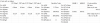
This seems to be about within the range of EL37, which were part of the original setup, but I'd need be able to reduce (increase, since it is negative) the bias within the 6L6GC range into -16/-20 range? Though it seems to be ok if I am operating them in 450 plate voltage, right?
My next step would be to pop in the rectifier tube only and get the dc voltages as well, yes?
Also am I correct to assume that I don't need the load resistors on the outputs, until I have all the tubes in?
This seems to be about within the range of EL37, which were part of the original setup, but I'd need be able to reduce (increase, since it is negative) the bias within the 6L6GC range into -16/-20 range? Though it seems to be ok if I am operating them in 450 plate voltage, right?
My next step would be to pop in the rectifier tube only and get the dc voltages as well, yes?
Also am I correct to assume that I don't need the load resistors on the outputs, until I have all the tubes in?
I think you might be fine for the grid voltage range but if not it can be changed later. If its overly negative, worst case it just won't flow enough current, so not that big of a problem for initial testing.
just make sure the DC voltages don't exceed any cap ratings. It will be on the high side with the power supply unloaded.
no need for dummy loads, it can't make any sound with no output tubes.
just make sure the DC voltages don't exceed any cap ratings. It will be on the high side with the power supply unloaded.
no need for dummy loads, it can't make any sound with no output tubes.
Rectifiers:
After turning over my stash for 5AR4's I found a few usable ones, including a Dynaco branded one! Did a quick test with a 5AR4 rectifier this morning, the voltage on the first filter gets right up to 450vdc (glad I put a 500v cap there, though the stock was 450v)
I'm interested to see how different it would work with a 5U4G, but should I? The original filter cap was 40uf at 450vdc, which is over the max spec of 32uf for 5U4. I replaced with 33uf at 500vdc, which is right at the max capacitance for 5U4 (32uf), so it should be OK, though I understand nominally 5U4 "likes" values closer to 20uf. Not knowing the specs of the power tranny, 5AR4 has a 1.9A filament as compared to 3A for the 5U4. I understand that often there is a generous margin the filament winding, but not sure if 1/3 isn't too much.
Output:
Other than the bias and the current my understanding is that 6L6GC could be plugged in instead of the EL37, at least for the voltages up to 450v, which is the case here, right? - the pinout is identical, the ratings are about similar, anything I am missing?
7027A, however is not a direct plug in because pin 1 is tied to G2 and pin 6 is tied to G1. On my amp pins 1-8 are tied together (why?) and pin 6 is used as a extra tie point, so at the very least I would have to undo that. Anything else I should be thinking about before I start changing things?
For testing purposes have 2 8Ohm 20W non-inductive wirewound resistors as the load. Looking at the spec sheet, I realize 2 6L6GC will make about 55W at 450v PP. For testing the voltages though, can I get by with those two at volume turned down, at least until I order bigger ones? I can mount them on CPU heatsinks for added heat dissipation. I understand that for max output measurements and distortion I would would probably use ones with 100w rating or so.
After turning over my stash for 5AR4's I found a few usable ones, including a Dynaco branded one! Did a quick test with a 5AR4 rectifier this morning, the voltage on the first filter gets right up to 450vdc (glad I put a 500v cap there, though the stock was 450v)
I'm interested to see how different it would work with a 5U4G, but should I? The original filter cap was 40uf at 450vdc, which is over the max spec of 32uf for 5U4. I replaced with 33uf at 500vdc, which is right at the max capacitance for 5U4 (32uf), so it should be OK, though I understand nominally 5U4 "likes" values closer to 20uf. Not knowing the specs of the power tranny, 5AR4 has a 1.9A filament as compared to 3A for the 5U4. I understand that often there is a generous margin the filament winding, but not sure if 1/3 isn't too much.
Output:
Other than the bias and the current my understanding is that 6L6GC could be plugged in instead of the EL37, at least for the voltages up to 450v, which is the case here, right? - the pinout is identical, the ratings are about similar, anything I am missing?
7027A, however is not a direct plug in because pin 1 is tied to G2 and pin 6 is tied to G1. On my amp pins 1-8 are tied together (why?) and pin 6 is used as a extra tie point, so at the very least I would have to undo that. Anything else I should be thinking about before I start changing things?
For testing purposes have 2 8Ohm 20W non-inductive wirewound resistors as the load. Looking at the spec sheet, I realize 2 6L6GC will make about 55W at 450v PP. For testing the voltages though, can I get by with those two at volume turned down, at least until I order bigger ones? I can mount them on CPU heatsinks for added heat dissipation. I understand that for max output measurements and distortion I would would probably use ones with 100w rating or so.
Last edited:
Oh, wait, I see what you're saying about the missing 680 ohm resistor. But I think that's just a safety load on the output to ensure the amp doesn't see no load at any point. He probably eliminated it, it's not used in the Mark IV or ST70, which also employ a 1K feedback resistor. But I could be wrong and 180 ohms is what he intended. Just seems too low to me.
Another goof-up - with some better lighting and some wiring out of the way, I can now see it is going to the yellow wire (not the orange), which is 16 Ohm tap, same as the schematic. (hmm now I wonder if the rest of my rewiring work was this lax
 )
)Pin 9 to yellow wire (16Ohm tap) from the output tranny measures 752Ohm on one and 794Ohm on the other side;
From 16Ohm tap to junction of the 680 and 47 measures about 41Ohm and 42 Ohm;
From 16Ohm tap to the chassis 1.1 Ohm;
Should I add the 680Ohm resistor, if it is a way to protect the pricey output trannies?