• The move to the new server is done. There are some software and database maintenance updates in process. This has us passing the hat around to help out. We appreciate any donations. Seriously, even a dollar helps. The payment page may be found here - https://www.audiokarma.org/support.html

Can anyone please help ID this amp?

I would check the coupling caps for leakage at rated volts before firing it up, i usually swap those out

I don’t have a leakage tester, but I suppose I could Frankenstein myself a hv dc power supply out of an old tranny utilizing some sort of a doubler/tripler circuit, then measure leakage directly.

Though not a substitute for the leakage test I tested them for capacitance in circuit and they all tested ok. That also tells me no shorts or opens.
 
A standard low voltage cap tester is usually useless for coupling caps, because they almost always fail as leakage at rated voltage. The easiest way to test the caps in circuit is to pull the output tubes, with the cap disconnected at the end that is a away from the high voltage, and measure between the cap and the chassis.
A good cap will show high voltage, and drain through through the meter to 0 volts
 
Last edited:
Interesting. Thank you.

Well, wait. According to your note included with your first attempt at tracing the circuit, there's a 270K resistor to pin 6 of the 6AN8, which only makes sense. A 47K load on the pentode plate would be way too low.

I can't account for the low value of the feedback resistor, but we shall see.
 
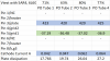
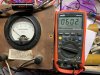
Did the final checks, assumed this is running AB1 PP. With published 6L6GC values of 450 Plate voltage, -37vdc g1 and 116mA for two tubes (88 mA each?) fired it up, bringing the bias up slowly to about -37 but aiming to stay under 70mA cathode current. Here's what I got:
My amp values 6l6gc.png

Sound-wise this thing is dead quiet and reproduces sound well. Will take a closer look at it through the oscilloscope later.
What should I actually bias it at?

4DA3DB6E-3A14-49B7-8017-12FF7C57AC4D.jpeg
 
Last edited:
Did the final checks, assumed this is running AB1 PP. With published 6L6GC values of 450 Plate voltage, -37vdc g1 and 116mA for two tubes (88 mA each?) fired it up, bringing the bias up slowly to about -37 but aiming to stay under 70mA cathode current. Here's what I got:
View attachment 2650033

Sound-wise this thing is dead quiet and reproduces sound well. Will take a closer look at it through the oscilloscope later.
What should I actually bias it at?

View attachment 2650038

Wow! Fantastic. 116mA for two tubes is 58mA each, which is a good level. You're at about 23 watts disspation per tube. But with 6L6GCs you could go higher, maybe 60-65mA each.

In terms of the scope, it would be nice to see some 10kHz square waves to see get an idea of the high-frequency response and also make sure it's stable. I would also check the amount of feedback. Dave Gillespie describes a process here:

https://www.audiokarma.org/forums/index.php?threads/citation-ii-hack.471242/page-3

Scroll down to #48.

Checking for power out at various frequencies would be interesting too.
 
Wow! Fantastic. 116mA for two tubes is 58mA each, which is a good level. You're at about 23 watts disspation per tube. But with 6L6GCs you could go higher, maybe 60-65mA each.

In terms of the scope, it would be nice to see some 10kHz square waves to see get an idea of the high-frequency response and also make sure it's stable. I would also check the amount of feedback. Dave Gillespie describes a process here:

https://www.audiokarma.org/forums/index.php?threads/citation-ii-hack.471242/page-3

Scroll down to #48.

Checking for power out at various frequencies would be interesting too.

Don't do math in your head or play with high voltage devices when sleepy. Yikes! o_O Will review that when I'm awake, thank you!
 
I've leak-checked caps in circuit with just a voltmeter. Install just the rectifier (or use a solid-state equivalent, thats even easier) and bring the voltage up with a variac, making sure to not exceed any ratings. Measure the voltage on the grid end of the coupling caps. It should be zero if its good. If you get more than a few millivolts, the cap is leaky and should be replaced.

or the trash can test works too. if it makes a noise when you throw it in the can, it was bad.
 
I've leak-checked caps in circuit with just a voltmeter. Install just the rectifier (or use a solid-state equivalent, thats even easier) and bring the voltage up with a variac, making sure to not exceed any ratings. Measure the voltage on the grid end of the coupling caps. It should be zero if its good. If you get more than a few millivolts, the cap is leaky and should be replaced.

or the trash can test works too. if it makes a noise when you throw it in the can, it was bad.

I've been monitoring the cathode current pretty closely. My understanding is if it is not climbing, then normally there isn't much leakage - that's why we care about dc leakage in the first place, no?

I heard of the trash can test, and I've done that with the main filter caps, but these vintage Astron mustard caps sound pretty good to my untrained ears, don't raise the cathode current and nowadays cost $20-25 a pop, that is if you can find them.

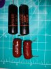
I do have the following worthy replacements if the need should arise:Caps on hand.jpg

Again, a complete newbie here, but my understanding is that the Astron mustard caps are paper in oil (PIO), and are most likely to develop leaks, the Elmenco, "brown drop" caps are dipped mylar, and the red Sprague "black beauties" are mylar/paper. Anecdotally, PIO seems to be the best for audio, then my guess would be black beauties, then the brown drops. However if someone wants to school me in capacitors, I'm all ears.

I forgot I have previously restored a SICO Model 76 cap tester, which has a leakage function, but my recollection is that leakage testing voltage is around 150vdc.

 
are they paper in oil or just straight paper? Most of those plastic shelled caps are just dry paper. The plastic isn't a great seal, and the paper wasn't usually super amazing quality to begin with so it can get acidic and start corroding the aluminum.

personally the only old caps I keep in things are film, and even then its only certain types. The EM brown drops hold up very well, some others go randomly open for some construction-related reason.
 
I've leak-checked caps in circuit with just a voltmeter. Install just the rectifier (or use a solid-state equivalent, thats even easier) and bring the voltage up with a variac, making sure to not exceed any ratings. Measure the voltage on the grid end of the coupling caps. It should be zero if its good. If you get more than a few millivolts, the cap is leaky and should be replaced.

or the trash can test works too. if it makes a noise when you throw it in the can, it was bad.

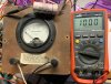
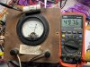
After poking around my junkbox, I found some tiny 12:1 transformers with twin secondary's out of an old UPS, I think. Flipped it around and it was good for about 375v with the variac output of about 30-35VAC. Theoretically should be 530VDC rectified, and a comfortable 1kv with a voltage doubler (though I think that exceeds the RMS limits of the 1N4007). Limited the current to 100uA (full scale of my ammeter) at 600v with the 3x2M resistors in series, so even if there is a dead short, I'm not going to smoke anything. Next step would be to lift one end of those vintage Astrons and see how they do. What am I looking for in these tests, an absolute zero leakage or is there an acceptable range?

Tested it out on a some old caps I had floating around. Here are some of the results:
img 3.jpg img 2.jpg img 1.jpg
 
You would have to look at the schematic and see if there is anything else across the capacitor, otherwise you have to lift one end of the cap to test.
 
.

In terms of the scope, it would be nice to see some 10kHz square waves to see get an idea of the high-frequency response and also make sure it's stable.

Checking for power out at various frequencies would be interesting too.

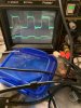
Downloaded one of them signal gen apps and also tried a pre-recorded square wave. Phone output is garbage. Unless I’m getting a cable resonance.
5AC268C7-5A56-4210-9EBC-25810CC50C29.jpeg
 
Downloaded one of them signal gen apps and also tried a pre-recorded square wave. Phone output is garbage. Unless I’m getting a cable resonance.
View attachment 2669008

Yeah, it's kind of hard to tell what's happening. If the lower trace is the input signal, it's not very clean. You should get an inexpensive signal generator from Amazon. I use a 2-channel Koolertron, it's pretty good for the money and puts out a clean-enough signal for this purpose.
 
Yeah, it's kind of hard to tell what's happening. If the lower trace is the input signal, it's not very clean. You should get an inexpensive signal generator from Amazon. I use a 2-channel Koolertron, it's pretty good for the money and puts out a clean-enough signal for this purpose.

The lower trace is just the other channel of the phone, but it looks identical to the upper trace. Very disappointing.

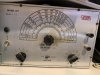
I could, but I already have an Eico model 377 on hand. Would that provide an acceptable square wave? If yes, that would be a bonus restoration project for me. If no, then I’d follow your advice on buying something suitable.

A4FC26F2-EDCF-4206-B2C3-D7E91CF79D0D.jpeg
 
Elenco has an inexpensive function generator.

Thanks for the tip! Curiously, the model FG500 goes for about $30-35, which is already cheap. At the heart of the device is the XR-2206 chip, and a quick search easily finds other xr2206-based devices in $10 or so range.
 
The lower trace is just the other channel of the phone, but it looks identical to the upper trace. Very disappointing.

I could, but I already have an Eico model 377 on hand. Would that provide an acceptable square wave? If yes, that would be a bonus restoration project for me. If no, then I’d follow your advice on buying something suitable.

View attachment 2669242

The Eico would surely better, yes, if it's in good condition. You can always see on the scope how clean it is. Certainly worth a shot.
 
Back
Top Bottom