• The move to the new server is done. There are some software and database maintenance updates in process. This has us passing the hat around to help out. We appreciate any donations. Seriously, even a dollar helps. The payment page may be found here - https://www.audiokarma.org/support.html

Can anyone please help ID this amp?

The step network seems excessive, and there is some ringing, I have to look at the schematic and get back to you, at least both channels are similar. Normally you should not do full power square waves, it's pretty hard on the amp.

 
The step network seems excessive, and there is some ringing, I have to look at the schematic and get back to you, at least both channels are similar. Normally you should not do full power square waves, it's pretty hard on the amp.

Thank you! Yeah my first real restoration project here, so I did not know that. I will make a note to not run square waves at full volume. Luckily that was just for a few seconds.

Not sure if this makes a difference with ringing specifically, but this was just a quick test within 5 minutes of the amp being turned on. I did not let the thing run for half an hour.

What does "the step network" mean?
 
I looked at the schematic, and there is no step network in your schematic, usually the step network is in the first tubes plate circuit, a resistor and cap in series across the plate resistor, to reduce the first overshoot in the square wave and it also does some rounding of the square wave leading edge.
You may want to change the 180 ohm resistor to 1K and check the 10k low powered square wave again.
The ratio of the 820 pf cap and the 180 ohm resistor, is very different from the Mark 3 the amp is copied from.
 
Last edited:
set the output level to about 2 volts peak to peak and see what it does. That will give a better picture without amplifier power output limitations skewing it.
 
set the output level to about 2 volts peak to peak and see what it does. That will give a better picture without amplifier power output limitations skewing it.

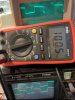
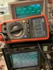
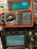
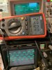
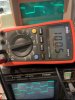
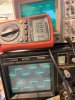
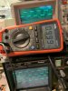
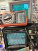
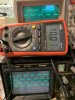
Here's my setup:
top scope is the probe on output of signal gen, frequency counter is clipped there too;
outputs from the amp via regular speaker wire to 100W load resistors mounted on the heat sink;
lower scope leads across the load resistors: top is left ch., bottom is right ch.;
Load.jpg

100Hz: 100Hz.jpg

1kHz: 1kHz.jpg

10kHz:10kHz.jpg

20kHz:20kHz.jpg

Under these conditions I can see oscillations at 10k and 20k. Next step: replace that 180Ohm resistor for a suitable 1K resistor, just like everyone told me a few times already. :) Can anyone approximate by eyeballing what is the wattage of that resistor? My guess is somewhere between 1 and 5 watt?
 
Oh and to set the output at 2VAC P-P, I set the sig gen for 500 Hz, at input, connected my meter at the output set to AC (my meter can measure AC up to 1khz) and set the output to ~.7vac, which should be just under 2VAC P-P. Did I get that right?
 
yep, thats fine. Just wasn't sure what the level was running at since an earlier post said something about "full". I wasn't sure if that meant full power or what. Running it way up will skew what you actually see on the scope.

The resistor off the plate won't actually be handling all that much power, but its dealing with a lot of voltage. The higher watt resistor was probably picked more for that reason than any other.
 
yep, thats fine. Just wasn't sure what the level was running at since an earlier post said something about "full". I wasn't sure if that meant full power or what. Running it way up will skew what you actually see on the scope.

The resistor off the plate won't actually be handling all that much power, but its dealing with a lot of voltage. The higher watt resistor was probably picked more for that reason than any other.


Yes, you understood it correctly. The previous set up was to look at the output at full amplifier output and at some random point at less than full (say 75%) while the load was a set of speakers;

My last post with pictures was at the amplifier output of 2 volts p-p as you suggested. I absolutely agree that my previous two setups did not show as clearly what was going on. (I'm assuming you can click on the thumbnail and it brings up enlarged image) Your suggested setup shows ringing clearly at both 10k and 20kHz, so thanks for the suggestions!
 
yep, thats fine. Just wasn't sure what the level was running at since an earlier post said something about "full". I wasn't sure if that meant full power or what. Running it way up will skew what you actually see on the scope.

The resistor off the plate won't actually be handling all that much power, but its dealing with a lot of voltage. The higher watt resistor was probably picked more for that reason than any other.

Sorry, I'm confused by the "resistor off the plate" comment, so I wanted to measure twice before I splice, so to speak. I am replacing the 180 ohm resistor (per channel, with a 1kohm) that goes from the 16 Ohm tap output to the cathode of the pentode on the 6AN8. Is that correct? I'm not confident in my ability to eyeball the wattage of the resistor, but Scott suggests Dynaco schematic has it as 1 watt. Lengthwise it measures around 17mm. Here: http://music.codydeschenes.com/wp-content/uploads/2013/06/abres.png it says 15mm is 1watt, 18 mm is 2 watt. I do have 1k 1watt metal oxide resistors on hand that I could use in that position, does that sound about right?
 
Last edited:
Using a 1 watt or 2 watt resistor is OK either way, The Dynaco schematic was 1 watt, but 2 watt will not hurt anything.
swapping with the 180 ohm is the correct thing to do.
 
Sorry, I'm confused by the "resistor off the plate" comment,

I was thinking of something else that isn't actually there. For some reason I thought the Dynaco had a resistor and cap from output tube plate back to the pentode and thats what you were talking about. Disregard. Its got just a 390pf cap from the screen.
 
I was thinking of something else that isn't actually there. For some reason I thought the Dynaco had a resistor and cap from output tube plate back to the pentode and thats what you were talking about. Disregard. Its got just a 390pf cap from the screen.

Ah thank you for clarifying. Now if the 1k resistor does not work well enough for some reason (I'll try that first), does putting there a 1k pot temporarily just on one channel to fine tune a resistance that will give the flattest response an option?
 
Ah thank you for clarifying. Now if the 1k resistor does not work well enough for some reason (I'll try that first), does putting there a 1k pot temporarily just on one channel to fine tune a resistance that will give the flattest response an option?

The feedback resistor value is determined by the amount of feedback it provides, in this case 20dB. You can check the amount of feedback with the procedure explained in this thread, comment #48.

https://www.audiokarma.org/forums/index.php?threads/citation-ii-hack.471242/page-3

In this case 1K should provide the correct amount.

Only then should the square wave response be fine tuned by adjusting the value of the phase-lead cap across the feedback resistor. Start with the original value in the schematic.

You generally don't tinker with the feedback level as a way of adjusting the amp's frequency response.
 
The feedback resistor value is determined by the amount of feedback it provides, in this case 20dB. You can check the amount of feedback with the procedure explained in this thread, comment #48.

https://www.audiokarma.org/forums/index.php?threads/citation-ii-hack.471242/page-3

In this case 1K should provide the correct amount.

Only then should the square wave response be fine tuned by adjusting the value of the phase-lead cap across the feedback resistor. Start with the original value in the schematic.

You generally don't tinker with the feedback level as a way of adjusting the amp's frequency response.

180Ohm replaced with 1KOhm. I put new waveform followed by the old waveform (with 180Ohm resistor) for ease of comparison. Here are the results:

100Hz:
100Hz 1k_fb_res.jpg - 1k 100Hz.jpg - 180Ohm res
1KHz:
1kHz 1k_fb_res.jpg - 1k 1kHz.jpg- 180Ohm res
10KHz:
10kHz 1k_fb_res.jpg -1k 10kHz.jpg - 180Ohm res
20KHz:
20kHz 1k_fb_res.jpg - 1k 20kHz.jpg - 180Ohm res
 
Last edited:
180Ohm replaced with 1KOhm. I put new waveform followed by the old waveform (with 180Ohm resistor) for ease of comparison. Here are the results:

100Hz:
View attachment 2698932 - 1k View attachment 2698947 - 180Ohm res
1KHz:
View attachment 2698928 - 1k View attachment 2698944- 180Ohm res
10KHz:
View attachment 2698930 -1k View attachment 2698945 - 180Ohm res
20KHz:
View attachment 2698931 - 1k View attachment 2698946 - 180Ohm res

It certainly looks more stable, much less ringing. The 1K resistor is taken from the 16 ohm tap, is that right? Did you leave the orginal phase-lead cap across it? More importantly, did you measure the amount of feedback? It's really important to ascertain that there is, in fact, 20dB of feedback before you do any more tests or fiddling with the components.
 
Back
Top Bottom