s-petersen
Scott
If you use a variac and bring it up slowly to form the can cap, and replace any paper caps in it, it should be good to go.


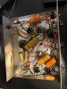

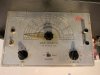
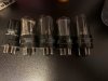

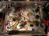

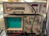
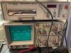
The Eico would surely better, yes, if it's in good condition. You can always see on the scope how clean it is. Certainly worth a shot.

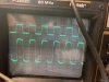
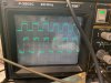
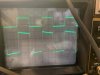
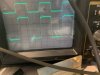
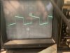
The 100 Hz looks slightly skewed, the 1k is spot on, and the 10k, is slightly rounded, as expected. Does that look about right, or do I have to do more troubleshooting on the sig. gen?
The specs for the Eico 377 say: Square Wave Range: 60-30,000c.p.s. (5% tilt at 60c.p.s., 5% rounding at 30 k.c.), so I wonder if it is within specs or if I need to follow some sort of adjustment procedure to make it perform better. The instructions (https://bama.edebris.com/download/eico/377/EICO 377 AF Sig Gen0001.pdf) seem to suggest some adjustments if "whenever tubes or other components are replaced"....They look like a pretty good tube amp, but not what you need for testing, unfortunately. They should be flat throughout the bandwidth of the generator.
Thanks for the tip, that's what I did along with the cans too, with the "before" and "after" pictures!If you use a variac and bring it up slowly to form the can cap, and replace any paper caps in it, it should be good to go.
The specs for the Eico 377 say: Square Wave Range: 60-30,000c.p.s. (5% tilt at 60c.p.s., 5% rounding at 30 k.c.), so I wonder if it is within specs or if I need to follow some sort of adjustment procedure to make it perform better. The instructions (https://bama.edebris.com/download/eico/377/EICO 377 AF Sig Gen0001.pdf) seem to suggest some adjustments if "whenever tubes or other components are replaced"....
That's still more experience than me at this point.Oh, well, maybe they're not far off then. I'm really talking through my hat a bit here, as they say--I have no experience with analogue generators.
 I'll fiddle around a bit more with the thing, try to get it more in shape, maybe try to follow some of the tune-up procedures, see if it helps. It already is a vast improvement over my cellphone and at least I can run a quick test at 1khz, that one does look good.
I think the square waves look off a little more than 5% , but I haven't used a tube audio frequency generator for square waves, most of my use is for RF
For audio my generators are solid state. I use a modified Heathkit 5218.and a BK E-310B
What value cap is C15? You can switch the 6K6s to see if it changes things.
I would measure the resistors around the 6SN7 tube as well
I think the square waves look off a little more than 5% , but I haven't used a tube audio frequency generator for square waves, most of my use is for RF
For audio my generators are solid state. I use a modified Heathkit 5218.and a BK E-310B
What value cap is C15? You can switch the 6K6s to see if it changes things.
I would measure the resistors around the 6SN7 tube as well


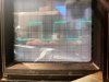
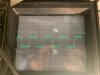
Will test that out, thanks!Sometimes as tubes wear, and age their characteristics change, bias points, gain etc, and switching points can change, switching tubes changed the operating points for the different functions.
I am not sure if the calibration setup will affect the square wave shape, I was just thinking that the slope in the output looked like there wasn't enough capacitance in the output for the lower frequencies. What kind of resistance is connected across the output terminals?
You could connect the o-scope at the input of C15 to see if it is flat before it.
Are your probes set to DC?, it helps...
Set it to DC, and check 100HZ again

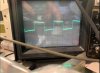

Wow! Fantastic. 116mA for two tubes is 58mA each, which is a good level. You're at about 23 watts disspation per tube. But with 6L6GCs you could go higher, maybe 60-65mA each.
In terms of the scope, it would be nice to see some 10kHz square waves to see get an idea of the high-frequency response and also make sure it's stable. I would also check the amount of feedback. Dave Gillespie describes a process here:
https://www.audiokarma.org/forums/index.php?threads/citation-ii-hack.471242/page-3
Scroll down to #48.
Checking for power out at various frequencies would be interesting too.
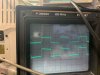 10kHz low:
 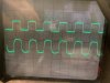 20kHz low: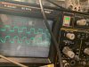
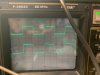 10kHz low:
 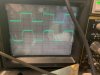 20kHz low: