• The move to the new server is done. There are some software and database maintenance updates in process. This has us passing the hat around to help out. We appreciate any donations. Seriously, even a dollar helps. The payment page may be found here - https://www.audiokarma.org/support.html

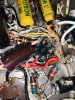
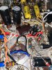
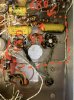
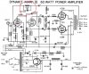
Can anyone please help ID this amp?

Another goof-up - with some better lighting and some wiring out of the way, I can now see it is going to the yellow wire (not the orange), which is 16 Ohm tap, same as the schematic. (hmm now I wonder if the rest of my rewiring work was this lax :oops:)
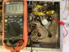
Pin 9 to yellow wire (16Ohm tap) from the output tranny measures 752Ohm on one and 794Ohm on the other side;
From 16Ohm tap to junction of the 680 and 47 measures about 41Ohm and 42 Ohm;
From 16Ohm tap to the chassis 1.1 Ohm;

Should I add the 680Ohm resistor, if it is a way to protect the pricey output trannies?

Hmmm, well okay. You need to disconnect the feedback loops to get proper measurements here. First I would disconnect the feedback loops from the input tubes and check the 680 and 47 ohms resistors on the cathodes. Probably best to replace them with high-quality 1% resistors to keep the feedback ration correct. With the loops still disconnected, measure from the input tube end of the loop back to the 16 ohm taps. Should be 1K. If not, I'd replace the feedback resistors so they match that.

I don't think you need the 680 ohm safety resistors.
 
Last edited:
The brown elyticap between #7&8 appears to be a provisional later addition, possibly to make up for a defective oem elyticap. See if there's a wire from 7 to chassis.

Well yes, that’s me butchering up the circuit. I’ve added a 2+ground lug strip and replaced the 40/40/40 @ 450 can and a 120@200v cans. Note the can in the middle disconnected from the circuit. Here’s the wider view:95507227-BD69-42D6-BD73-31FD0750895B.jpeg

The way it sits, I can probably make a loop on both ends of the diode, crimp and solder one directly to the wire, the other end directly to the lug and just heatshrink the whole caboodle.
 
Last edited:
Well yes, that’s me butchering up the circuit. I’ve added a 2+ground lug strip and replaced the 40/40/40 @ 450 can and a 120@200v cans. Note the can in the middle disconnected from the circuit. Here’s the wider view:View attachment 2648821

The way it sits, I can probably make a loop on both ends of the diode, crimp and solder one directly to the wire, the other end directly to the lug and just heatshrink the whole caboodle.
Yes, you could do that, others have.
Of course, mind the polarity of the diodes.
 
Hmmm, well okay. You need to disconnect the feedback loops to get proper measurements here. First I would disconnect the feedback loops from the input tubes and check the 680 and 47 ohms resistors on the cathodes. Probably best to replace them with high-quality 1% resistors to keep the feedback ration correct. With the loops still disconnected, measure from the input tube end of the loop back to the 16 ohm taps. Should be 1K. If not, I'd replace the feedback resistors so they match that.

I don't think you need the 680 ohm safety resistors.

Sorry, this is going right over my head. But I do thank you for the effort it takes to explain and for the knowledge that you have accumulated and are willing to share.

I sort of understand why feedback but not how it works. I’m thinking you take a portion of the output signal, feed it back into some point in the circuit, usually a cathode of a previous stage and because the signal is essentially inverted, it cancels out distortion but also part of the signal. Too much feedback and it does what - stops giving you distortion improvements but saps your signal? I understand that 1k is a customary value for this type of amp(and I’ll probably go with that), but for teh sake of my own understanding why didn’t they do that initially? Can there be another reason why they’d do that, maybe to control oscillations? Here’s a crudely traced circuit:
EF16419E-BC8D-4DB6-8084-99025253574A.jpeg
The hidden end of the 680 goes to pin 9, and 47 to socket center lug ground.

And at least in theory I should be getting 180+680= 860Ohm - is that close enough to 1k or no?

794Ohm seems to be within 7% spec of the 10% resistor tolerance and 752 Ohm is at 12.5%, though you did say the caps in circuit would skew this a bit. Is this considered to be out of spec?

Also would this 42 Ohm difference in resistance between the channels and therefore the amount of feedback be audible?

Would it make any difference if I replace these resistors with metal oxide ones?

 
Last edited:
Sorry, this is going right over my head. But I do thank you for the effort it takes to explain and for the knowledge that you have accumulated and are willing to share.

I sort of understand why feedback but not how it works. I’m thinking you take a portion of the output signal, feed it back into some point in the circuit, usually a cathode of a previous stage and because the signal is essentially inverted, it cancels out distortion but also part of the signal. Too much feedback and it does what - stops giving you distortion improvements but saps your signal? I understand that 1k is a customary value for this type of amp(and I’ll probably go with that), but for teh sake of my own understanding why didn’t they do that initially? Can there be another reason why they’d do that, maybe to control oscillations? Here’s a crudely traced circuit:
View attachment 2648878
The hidden end of the 680 goes to pin 9, and 47 to socket center lug ground.

And at least in theory I should be getting 180+680= 860Ohm - is that close enough to 1k or no?

794Ohm seems to be within 7% spec of the 10% resistor tolerance and 752 Ohm is at 12.5%, though you did say the caps in circuit would skew this a bit. Is this considered to be out of spec?

Also would this 42 Ohm difference in resistance between the channels and therefore the amount of feedback be audible?

Would it make any difference if I replace these resistors with metal oxide ones?

Okay, here goes:

Your understanding of feedback is correct. Global feedback, which includes the output transformer, lowers distortion and increases the frequency response of the circuit, especially the output transformer. Too much feedback and you not only reduce the gain too much but you reach a point of instability. Nuff said!

Now look at the schematic. The 1K feedback resistor and the 47 ohm resistor to ground form a voltage divider, sending a partion of the output signal back through the 680 ohm resistor to the cathode of the input stage. Okay.

Here's the tricky part. The 680 ohm cathode resistor is not part of our voltage divider for the feedback. The 1K resistor and the 47 ohm resistor form the voltage divider.

So with the feedback resistor connected, and measuring from that junction to ground, you are measuring 47 ohms *in parallel* with 1K from the 16 ohm tap. Thus you get slightly less than 47 ohms. 45 ohms would be the actual correct measurement.

What you need to do is *disconnect* the striped wire from the tag board that connects it to the 47 ohm resistor. Then measure from the 16 ohm tap to *the end of that wire*. I'm quite sure you will see more than 180 ohms.

Sorry to drag this out but it's important to make sure that the amp is properly designed, which it certainly seems to be.
 
Last edited:
Okay, here goes:

Your understanding of feedback is correct. Global feedback, which includes the output transformer, lowers distortion and increases the frequency response of the circuit, especially the output transformer. Too much feedback and you not only reduce the gain too much but you reach a point of instability. Nuff said!

Now look at the schematic. The 1K feedback resistor and the 47 ohm resistor to ground form a voltage divider, sending a partion of the output signal back through the 680 ohm resistor to the cathode of the input stage. Okay.

Here's the tricky part. The 680 ohm cathode resistor is not part of our voltage divider for the feedback. The 1K resistor and the 47 ohm resistor form the voltage divider.

So with the feedback resistor connected, and measuring from that junction to ground, you are measuring 47 ohms *in parallel* with 1K from the 16 ohm tap. Thus you get slightly less than 47 ohms. 45 ohms would be the actual correct measurement.

What you need to do is *disconnect* the striped wire from the tag board that connects it to the 47 ohm resistor. Then measure from the 16 ohm tap to *the end of that wire*. I'm quite sure you will see more than 180 ohms.

Sorry to drag this out but it's important to make sure that the amp is properly designed, which it certainly seems to be.

Nothing to be sorry about, that’s how troubleshooting works, if anything I appreciate your time and advice.

So I don’t see in the schematic the 1k resistor you are talking about, unless your explanation assumes the 180ohm resistor currently in circuit being replaced with a 1k as you suggested earlier. Is my understanding correct?

I followed your instructions in disconnecting the striped wire from the tag where it meets 47 and 680, measured resistance from that end to 16 ohm tap, here’s what I get:
700E9241-D3BF-4146-9B60-A4E7E5BFE0CA.jpeg
 
Nothing to be sorry about, that’s how troubleshooting works, if anything I appreciate your time and advice.

So I don’t see in the schematic the 1k resistor you are talking about, unless your explanation assumes the 180ohm resistor currently in circuit being replaced with a 1k as you suggested earlier. Is my understanding correct?

I followed your instructions in disconnecting the striped wire from the tag where it meets 47 and 680, measured resistance from that end to 16 ohm tap, here’s what I get:
View attachment 2649363

The 1K feedback resistor is circled in the attached schematic, same as yours except you have it relabelled as 180 ohms. That makes no sense to me. That's injecting a huge amount of feedback into the input stage. The amp looks competently built, I just can't understand why the feedback resistor is so low in value. There must be something else going on that I don't understand. Maybe someone else can make a suggestion.

7F1337C9-048C-44B3-AB35-334EFCBC9CD4.jpeg

ETA: Also, I know the A-420 is a different transformer from the A-431, with a higher primary impedance (6.6K as opposed to 4.3K), so the feedback resistor would be a little different from the Mark III schematic, but it still seems way too small to me. Maybe it's right. I guess you'll need to get the amp ready to fire up and see if it works.
 
Last edited:
The 1K feedback resistor is circled in the attached schematic, same as yours except you have it relabelled as 180 ohms. That makes no sense to me. That's injecting a huge amount of feedback into the input stage. The amp looks competently built, I just can't understand why the feedback resistor is so low in value. There must be something else going on that I don't understand. Maybe someone else can make a suggestion.

View attachment 2649388

ETA: Also, I know the A-420 is a different transformer from the A-431, with a higher primary impedance (6.6K as opposed to 4.3K), so the feedback resistor would be a little different from the Mark III schematic, but it still seems way too small to me. Maybe it's right. I guess you'll need to get the amp ready to fire up and see if it works.

I was hoping you’d say that. Let’s fire the sucker up! Any feedback on my suggested use of 6L6gc tubes and 20watt load resistors?
 
Oh hell no....I applaud anyone who dives into that....would scare me...

In my opinion as long as you follow the basic safety precautions when working with appliances that run at high voltages, it is fun and rewarding hobby on many levels. Plus all the advice and support on this forum.

This is my first power amp project and I have zero formal study or training. So if I can do it, anyone can. I started by looking at some very basic circuit schematics, 1-2 tubes like ones in turntables.
 
Output:

Other than the bias and the current my understanding is that 6L6GC could be plugged in instead of the EL37, at least for the voltages up to 450v, which is the case here, right? - the pinout is identical, the ratings are about similar, anything I am missing?

7027A, however is not a direct plug in because pin 1 is tied to G2 and pin 6 is tied to G1. On my amp pins 1-8 are tied together (why?) and pin 6 is used as a extra tie point, so at the very least I would have to undo that. Anything else I should be thinking about before I start changing things?

For testing purposes have 2 8Ohm 20W non-inductive wirewound resistors as the load. Looking at the spec sheet, I realize 2 6L6GC will make about 55W at 450v PP. For testing the voltages though, can I get by with those two at volume turned down, at least until I order bigger ones? I can mount them on CPU heatsinks for added heat dissipation. I understand that for max output measurements and distortion I would would probably use ones with 100w rating or so.

Here are my thoughts on the 6L6gc and load resistor, so you don’t have to look for it. Am I ok using that as a plug-in sub for EL37? I can start with the lowest negative bias and work my way up.

Also I found a nice analog ammeter in my stash for checking current. (Will do 1ohm sense resistor later). The ground issue in tube 4 was fixed by cleaning the contacts on the 1/4 jack.

Oh and I could use properly rated speakers as my load. First tests are no signal anyway.
 
ETA: Also, I know the A-420 is a different transformer from the A-431, with a higher primary impedance (6.6K as opposed to 4.3K), so the feedback resistor would be a little different from the Mark III schematic, but it still seems way too small to me. Maybe it's right. I guess you'll need to get the amp ready to fire up and see if it works.
In addition to the differences in the output transformers, OP has 47K from supply to pin 6 in his input stage while your schematic has 270K there. The gain of the input stages (and thus the open loop gains) are quite different but including the effect of the different feedback resistors (180 vs. 1K) the resulting loop gains are similar.
 
Last edited:
In addition to the differences in the output transformers, OP has 47K from supply to pin 6 in his input stage while your schematic has 270K there. The gain of the input stages (and thus the open loop gains) are quite different but including the effect of the different feedback resistors (180 vs. 1K) the resulting loop gains are similar.
Interesting. Thank you.
 
Back
Top Bottom