• The move to the new server is done. There are some software and database maintenance updates in process. This has us passing the hat around to help out. We appreciate any donations. Seriously, even a dollar helps. The payment page may be found here - https://www.audiokarma.org/support.html

Capehart 114N2 6L6 Amp Pics+Restoration

AlexHempel

AK Subscriber
Subscriber
Hi everyone,

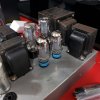
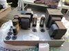
This just arrived on my doorstep today. Purchased from the auction side, seller had no idea what it was (listed as "1950s tube amp big transformers.") Hilarious amount of iron on this thing, although it's not as heavy as I expected. The big one is the PT of course, and the OPT is next to it. The other two are large chokes. In the console, it would have powered the receiver as well, which explains the extremely overbuilt power supply. I got the schem from radiomusuem.org, as one would expect the circuit is very simple. Four 6J5s: one preamp, one phase inverter, and two drivers, connected to 6L6s in push-pull with cap coupling. Dual 5U4G rectifiers. For this reason, I figured it would be a good introduction to tube restoration. For some odd reason, it came with three 5U4Gs, and the Ebay listing pics showed one 5U4G plugged into a 6L6 socket. Hope they didn't turn it on like that.

Unfortunately, the transformers are quite rusty, and the chassis paint is peeling (and probably leaded). Once I've verified that the transformers are good, I'm probably going to get it sandblasted and powdercoated. Anyways, here are some pics, figured you guys might enjoy seeing this one. Open to any suggestions on how to use this -- I don't have a mono setup or anything. Ideally I'd find a second, but who knows how long that'll take.
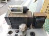
20200807_104008.jpg

20200807_104033.jpg

20200807_104015.jpg
 
Register to hide this ad
I really hope the iron isn't shorted out or rusted through. There are gaps in the paint/laminations and there's mold on some of the cloth wires, so I suspect it might've been in a damp area.
 
Anyone have advice for cleaning moldy cloth wires? I saw an old AK thread where someone mentioned using a dilute bleach solution. Wondering if anyone has other ideas?
 
Don’t get the laminations of the transformers sandblasted. I believe it may damage them. Just rub down lightly by hand and refinish. No problem with sandblasting the covers, if removed, of course.
 
@Dandy That makes sense, especially if the sandblasting is aggressive. And who knows what'll happen if I send it off to a shop. I kind of want them powdercoated though -- does powdercoating work without complete removal of the paint? I would just use sandpaper, but I'm concerned about lead in the paint and don't really want to contaminate my back yard with lead paint dust.
 
I usually lightly wire brush to get the scaly crap off the lam stack and spray paint it. The bells you can get more aggressive with. These wouldn't have had lead based paint, its just common enamel, same as spray paint today.
 
When i worked in a production environment we would send truckloads of parts to the powder coater. The first step in their process is to sandblast everything. Knowing that, id send my chassis with the paint on it, let them do the dirty work, because they're going to do it anyway.
 
Ok, resurrecting this thread because I've decided to begin work again on the Capehart, which I've learned is an "N2" model amplifier. It was used in the 114N2 and a few other similarly-priced consoles. I spent a bunch of time scrubbing all the transformers and chokes today; I used a brush with hard plastic bristles and some slightly-soapy water. It did clean up pretty nicely, hopefully no damage to the laminations. Also weighed it: 35 lbs, of which at least half is that ridiculous PT.

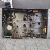
I took inventory of the underside to check which resistors need replacement. The schematic includes the proper resistances and voltages for every pin of every tube socket, which is extremely useful. All the high-power resistors (two wirewound 250 ohms and a 5.6k 30w dropping resistor) measured very close to spec; the 5.6k was within 1%! Unfortunately, the carbon comp resistors haven't fared very well, so I plan to replace all of them.

In addition, the caps appear to be shot, so I'm going to fully recap. Planning on new 40x20x20uf can caps for the main filters. For connectors, I bought a new aux jack matching the obscure original and plan on using a 32a Powercon (because it matches the existing hole spacing) in place of the original two-prong male receptacle. Still have no idea what to do for speaker connection or the power switch.

I did find one issue while poking around: someone appears to have shorted the heater wiring to the chassis and made other alterations to the heater circuitry. The heater is supposed to have a 20k resistance to ground, so this is definitely some sort of modification. Glad I caught the mess before turning it on.

Here's a pic of the somewhat cleaner amp with tubes installed:

20201205_193028.jpg
 
wirewound resistors generally stay on value, or they have been burned open. Not a whole lot else that can happen there. CC resistors, not so reliable.
 
On my Allen Organ C3s, which are probably from the same era, all the CC resistors were off values. They all need to be replaced IMO.
Even if they test good now, they may drift tomorrow. And they drift more with temperature that metal film.

As Gadget says, all WW resistors can stay. I've never saw one drift, they all die open.

The electrolytic caps were still good, after a very slow start over several hours. I would replace them for piece of mind.
The bad one will start to get hot and that's the sign.

The coupling caps were all totally leaky and again IMO all need to be replaced.
Once you do all this, these amps will outlast all of us.
 
Alright, the order is in. A lot of money to spend on an amp that may or may not sound good, but I hate doing half-assed restorations, so I'm gonna give it the best possible chance. The multi-segment can caps are especially bad on the cost front, but the existing can caps are pretty beat up, so I want to get rid of them, and the amp would look weird without new ones. Also bidding on a variac so I can bring it up properly.
 
@gadget73 Yeah, I feel the same. Once I get something running properly, my interest in working on it fades. If it breaks afterwards or needs some other modifications, I don't have much motivation to go back.

@Erhard-Audio Here you go! Sorry for the bad pictures, lighting is a bit wonky. Honestly, the layout of this amp is infuriating -- tons of un-used space in the middle, all the preamp stuff crammed into the top left corner. Also, I need to bypass that relay at the bottom right. As far as I can tell, it prevents the amp from turning on without the umbilicals for the other console parts plugged in.

20201206_160628 (1).jpg

20201206_160721 (1).jpg

20201206_160712 (1).jpg
 
looks easy enough to work on at least. Tons of space. Looks very 1940s inside. My EH Scott 800b has some similarities with the bundled wiring. Mildly annoying when you need to trace something out, but it looks a lot better than the bowl of spaghetti mess that a lot of things are.
 
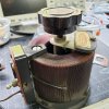
Look what arrived today! Now I'm finally ready to get working on the amp -- once I have time, that is.

I have one quick question about variac polarity. The variac's cord is non-polar, but the outlet is polar. How does this work? Will the outlet polarity be correct regardless of which direction the cord is plugged in, or is the outlet polarity meaningless and they just happened to use a polar outlet? I want to make sure I figure out the correct variac polarity, because I plan to wire the amp with proper switch polarity and without the death cap.

20201212_132352.jpg
 
Back
Top Bottom