• The move to the new server is done. There are some software and database maintenance updates in process. This has us passing the hat around to help out. We appreciate any donations. Seriously, even a dollar helps. The payment page may be found here - https://www.audiokarma.org/support.html

Capehart 114N2 6L6 Amp Pics+Restoration

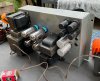
I realize now that I should have done the heaters first so they could be closer to the chassis for shielding. However, getting my 20awg solid core wire flush with the chassis would have been extremely difficult, so I'm not sure the end result would have been much better that way.
 
Got around to powering it up today. It's certainly amplifying something, because the speaker output hums quite a bit. I'm used to SS, so I'm not sure how this compares to other 1940s-era amplifiers. Certainly audible at 80v line, but wouldn't be noticeable with moderate volume music superimposed. With my 200w bulb I couldn't get the line voltage above 80v with the variac -- turning further increased the brightness of the bulb but the voltage didn't budge despite going well past the 1:1 turns ratio. For reference plate voltage was around 200 at this point and 6L6 bias was around 11v. Does this indicate an issue of some sort? All voltages at the tube sockets look good (about 2/3 of the correct value at full line).

On Tuesday I'll try feeding it signal on a 300w bulb. As of now, there's no coupling cap on the input, so I need to check my sources for DC or add one.

image1 (2).jpeg

image0 (5).jpeg
 
Cool. Just a question. As you confirmed that the voltages are proportionally correct, why do you still need a bulb in your test circuit?
If your Variac has a current gauge, or a killawatt box, just watching the current as you adjust the voltage with your Variac should be safe enough?
Just curious. Thanks.
 
@Brice My variac doesn't have an ammeter, and I didn't have a spare meter for that purpose, so I wanted to keep the bulb in circuit. Also, my temporary wiring bypasses the mains fuse. I'm running it now with a 300w bulb and it sounds great.

Also gadget's instinct was correct -- having a real input cut the hum substantially. It's still audible close to the speaker with no music playing, but you'd never notice otherwise. And my mains and input wiring is alligator clips -- proper shielded cable might help further. Now I've just got to mount the power switch, powercon receptacle, and binding posts and it'll be complete. They're going to be mounted to plywood since I think the chassis is cad plated and I'd rather not drill into that.
 
Once I've got everything wired up properly I'll post scope shots of square wave and try the frequency response as well.
 
see if the remaining hum is 60 or 120. 60 would imply some grounding issue or noise pickup from the heater supply. If its 120 thats probably either a supply filtering issue or unbalanced output tubes. If the current doesn't match, you'll get a bit of 120 at the speaker as a result.
 
@Brice My variac doesn't have an ammeter, and I didn't have a spare meter for that purpose, so I wanted to keep the bulb in circuit. Also, my temporary wiring bypasses the mains fuse. I'm running it now with a 300w bulb and it sounds great.

Also gadget's instinct was correct -- having a real input cut the hum substantially. It's still audible close to the speaker with no music playing, but you'd never notice otherwise. And my mains and input wiring is alligator clips -- proper shielded cable might help further. Now I've just got to mount the power switch, powercon receptacle, and binding posts and it'll be complete. They're going to be mounted to plywood since I think the chassis is cad plated and I'd rather not drill into that.

A cheap solution I used was to buy a device like a Kill A Watt and plug it into the variac output. A handy little device to have on hand and quite inexpensive.
 
Once I move into a new apartment I'm planning on making a panel with a variac, DBT, line fuse receptacle, panel ammeter, and panel voltmeter all wired together. DBT and variac will be bypass-able with switches. But might also get a kill-a-watt; they look convenient for testing on the fly. Right now I use a clamp ammeter with a line cord patch that exposes one of the wires to get readings, but it was out of battery when I fired up the N2.
 
I used to do it that way, but my clamp-on is so old that its an analog meter. No batteries needed unless I want to use the ohms range. I'm kind of a fan of non-battery things where practical purely because its one less thing I have to deal with. Also I got it really cheap.
 
Well I was going to square wave test but I don't have a proper signal generator yet (another thing to buy after I move). Tried using one of those phone-based tone generators but the output was ringing horribly before even going into the amplifier. And it wasn't my probes because I tested them with my scope's built in 1khz square wave gen and that looked perfectly fine.
 
Ran the amplifier today without a variac or DBT and the power supply is somewhat problematic. I think the issues stem from the absence of the tuner as a load. I'm already using a bucking transformer configured to drop 12v since my line is, of course, over 120. With the bucking xfmr, I get 370v on B+ -- a little high but within 10% of the correct value. However, the heaters are running around 7.3v and the power tubes have 24v and 23v of cathode bias, which is much higher than the correct value of 18.5v. Obviously I cannot run the amplifier for an extended period of time in this state, as the 6L6s are dissipating over 30w and the heaters are getting fried.

Also, the hum is back with a vengeance. I added mains earth but it sounds like 120hz and not a ground loop. I'm guessing the correct approach is dropping resistors, but unfortunately I don't plan on bringing this amplifier with me in the move (at least not initially), so it might be a project for later.
 
Last edited:
are you using one of the extra heater windings as a bucking coil? Should be able to do that to drop ~6v effectively off the line. 7.3v on the heater supply is much too high though. I usually target 6.3v at the heaters and let the rest fall where it may. +/- 5% won't bother anything. I think officially RCA allows 10% variance but I don't like to run things at the high end of tolerance just because it leaves no room for line fluctuations.
 
Right now I'm using a 12VCT heater trafo, not one of the heater windings. That's an interesting idea, I guess I could drop six more volts. But even with another 5% reduction in line voltage the heaters would still be high. I think it needs a dedicated solution
 
why are you using an external heater transformer? Looks like the stock transformer has 3 sets of windings. With low load on the main power transformer the B+ will end up overly high too. With a load on that main transformer it may very well settle itself out. One winding per channel, and the third as a bucking winding would probably work out OK.
 
To be completely honest, I did not know you could just add the heater windings in series with the primary to drop voltage. I'm still figuring out transformers, but it does make sense intuitively, since you're just increasing the turns in the "primary." I will give it a shot tonight.

Beyond the change in turns ratio, will loading those heater windings increase the voltage on the other windings? I thought voltage drop was specific to the turn being loaded.
 
no, if wired in properly it basically acts like the primary is longer, changing it from a 117v to a 123v coil. The rest of the windings will drop by ~5%. The only trick is the phasing, get it wrong and it boosts the voltage by 5%.

I'm using that setup in my Magnavox 9300, works pretty well. Heaters run at 6,2v right out of the wall. Used to run about 6.7v
 
Back
Top Bottom