

You are using an out of date browser. It may not display this or other websites correctly.
You should upgrade or use an alternative browser.
You should upgrade or use an alternative browser.
CR-1020: After recap stuck in protection SOLVED
- Thread starter Johnny_Law
- Start date
-
- Tags
- cr-1020 transformer

Broken wire? Cold solder?
Some of the glue had melted into a solder joint of one of the capacitors, which I saw as I removed it to check it but didn't think much of. I cleaned it and re-soldered it. Then when I connected the E. Cap board to the PS board, my FM radio reception on my bench receiver went out for a second as if there was some interference all of a sudden, which hadn't happened any of the other times I had re-connected the boards. But then it clicked out of protection briefly once. So I touched TR712 and CLICK.
Here's what I saw underneath TR712.

I wiggled it, saw one solder pad was loose, so I went to remove the solder and the whole dang thing came off.

I jumped it with a wire and now we're back in business.
I put the Nichicon caps all back in at C805/C806 and it continues to come out of protection.
Last edited:
Poetic irony, here. Back when I posted this, the narrator probably said, "Little did he know, the theory very much held water". 
Found a second person with the exact same symptoms as me ... but the thread was never resolved.
Starting to sound like a common issue. But, my 2SD234s are gone (TR712, TR715 replaced with TIP31A) so I don't know if this theory holds water.

Super...All's well that ends well.
Thanks so much for all the help.
I'm having very much the same problem with the 1020 I've been rebuilding. I read through the entire thread and took from it what I can. Here's what I've done so far. Replaced all caps (electrolytic) on the PS Board, Replaced all on the Cap board including the two 15,000 uF. Replaced the caps on both main amp boards. When I got the unit, it was bouncing in and out of protection. Now it's stuck in protection with the tuning meter at 50%. (So much for a ton of work so far). I did check the 36 VAC outputs at the ecap board and they are right on 36 VAC. When I had the boards out, I checked for the glue issues and for cold solder joints etc. I jumpered a couple of lifted traces and made sure they were good. I checked the output transistors with the DCA 55 and they are good. Cleaned and reinstalled with new thermal grease.
Geez, at this point I'm getting a little depressed. As I reinstalled the boards after rebuild, I verified all lifted leads with the schematics to double check everything landed correctly, even though I did use Brady markers. Also installed a new protection relay when I rebuilt the PS board. Seems like a lot of folks have gone through this drill on a 1020. I would appreciate knowing what voltage readings after all that everyone else has been through, would be the most likely to tell me something. As anyone knows that has gone through this, these boards don't like being pulled since a lot of the lighter weight leads have a tendency to break off. Hate to pull boards again unless I can figure out what the heck is a likely culprit. Help appreciated.
Geez, at this point I'm getting a little depressed. As I reinstalled the boards after rebuild, I verified all lifted leads with the schematics to double check everything landed correctly, even though I did use Brady markers. Also installed a new protection relay when I rebuilt the PS board. Seems like a lot of folks have gone through this drill on a 1020. I would appreciate knowing what voltage readings after all that everyone else has been through, would be the most likely to tell me something. As anyone knows that has gone through this, these boards don't like being pulled since a lot of the lighter weight leads have a tendency to break off. Hate to pull boards again unless I can figure out what the heck is a likely culprit. Help appreciated.

This thread is almost a year old...mgl99, You might get more help if you start your own thread. I just started a very similar thread for my CR-1020. What are your voltages at TR702?

craigsc
Active Member
LOL, I misread the date!This thread is almost a year old...

Just had a very similar issue. Bias and DC as they should be but wouldn't flip the relay.
TR702 had ~19V on E and B and close to zero on C.
Turned out to be bad connection on the connector pins from the Filter Capacitor board AND bad connection to TR712 just like this one, and bad connection at TR702.
The traces on these boards as not to mess with ...
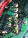
Here you can see the connector pins with degraded solder from mechanical movement and heat.
TR702 had ~19V on E and B and close to zero on C.
Turned out to be bad connection on the connector pins from the Filter Capacitor board AND bad connection to TR712 just like this one, and bad connection at TR702.
The traces on these boards as not to mess with ...
Here you can see the connector pins with degraded solder from mechanical movement and heat.
Last edited:

Good job & thanks for the info. These old Yammies were design engineered so well that today's problems often result from simple physical/mechanical faults like that. I say simple with humility cuz it seems that way when we finally find them. But can take time to find them. Wish they were sold with a magnifying glass in the box.Just had a very similar issue. Bias and DC as they should be but wouldn't flip the relay.
TR702 had ~19V on E and B and close to zero on C.
Turned out to be bad connection on the connector pins from the Filter Capacitor board AND bad connection to TR712 just like this one, and bad connection at TR702.
The traces on these boards as not to mess with ...
Here you can see the connector pins with degraded solder from mechanical movement and heat.
View attachment 3127305
Last edited:
Good job & thanks for the info. These old Yammies were design engineered so well that today's problems often result from simple physical/mechanical faults like that. I say simple with humility cuz it seems that way when we finally find them. But can take time to find them. Wish they were sold with a magnifying glass in the box.
I have two magnification LED lamps. Blind as a bat without them
