

You are using an out of date browser. It may not display this or other websites correctly.
You should upgrade or use an alternative browser.
You should upgrade or use an alternative browser.
CR1020 Restoration Guidance

LFazio51
Active Member
Note : The white plus sign above the black cap in the photo And.. the present polar orientation of said black cap..
Oh wow, I originally thought you were referring to the large filter cap - which was installed according to according to pcb markings, and was sitting here confused. Upon closer inspection though, I can see that you're referring to the 1000uf/50v cap - thanks much for the warning. I'd really hate to invest the amount of time and enegry in this project and have a stupid mistake like that happen. REALLY APPRECIATE IT!


If and when you go to replace that 1000µf cap don't rely on the circuit board silkscreening.. There are mistakes.Oh wow, I originally thought you were referring to the large filter cap - which was installed according to according to pcb markings, and was sitting here confused. Upon closer inspection though, I can see that you're referring to the 1000uf/50v cap - thanks much for the warning. I'd really hate to invest the amount of time and enegry in this project and have a stupid mistake like that happen. REALLY APPRECIATE IT!
LFazio51
Active Member
Whenever time permits, please take a look at the same photo - notice the 6-pin male terminals that connect to the main power supply board - it's chipped, and if you scroll back through this thread, you will notice a photo where I indicated the pin broke lose due to a cold solder joint on the back side. Initially I thought I was going to simply solder the pin back in but didn't realize there was a plastic base, that once again, due to what appears to be "heating," broke when the pin came out of the board. My thoughts are to replace the entire terminal strip for greater stability; I believe re-soldering just the pin won't be very stable and likely break lose when I try to connect the power supply board once more. As always, any thoughts or suggestions would be greatly appreciated.
Might be able to find something at Mouser or Digikey.My thoughts are to replace the entire terminal strip for greater stability
LFazio51
Active Member
Whats the pin spacing in mm's ? and the pin length ?
The height of the plastic base is roughly 3mm, pins are 11mm in length from the top of the plastic base, and they are on 4mm centers. I'm probably going to need another 3-4mm of length under the plastic base to go through the pcb as well.
LFazio51
Active Member
Might be able to find something at Mouser or Digikey
I think I found something that will work at Mouser.
https://www.mouser.com/ProductDetai...iMZZMs%2bGHln7q6pm0R%2bIqgWC%2bQxHkhkhiz4huc=
Looks like a pretty close match to me.I think I found something that will work at Mouser.
https://www.mouser.com/ProductDetail/Molex/26-20-2061/?qs=sGAEpiMZZMs%2bGHln7q6pm0R%2bIqgWC%2bQxHkhkhiz4huc=
LFazio51
Active Member
Ok, given the fact that this is my first project, there is much to repair, and I'm a little unsure of my ultimate success, I decided to go with a lesser expensive filter cap than the Nichicon Fine Golds. If I had more experience at this level, I'd have no problem spending the money but at this point, I'd like to save $30 and see if I can get it up and running with the Nippon Chemi-Con's I just purchased (link below). They are 40mm x 63mm with a 22mm pin spacing that I think I can make work. I also placed my first order of capacitors so all of these items should be arriving tomorrow. 
https://www.mouser.com/ProductDetai...GAEpiMZZMsh%2b1woXyUXjxxbWNj7/LcIDXkfJBdRSQE=
https://www.mouser.com/ProductDetai...GAEpiMZZMsh%2b1woXyUXjxxbWNj7/LcIDXkfJBdRSQE=

LFazio51
Active Member
I finally performed my first filter cap removal and believe it was successful. Lots of solder on them there pads and it appears that I was able to properly suck enough away to remove the caps without damaging the pads or the boards - Yay! (pics attached)
Now that they are removed, I'm becoming more and more curious as to WHY the left part of this board is discolored along with the left side of the 6-pin molex connector (pic below). It seems to me that this concern warrants some additional consideration as it could be the result of why the receiver wasn't performing properly, and therefore should be investigated to ensure there is no need to return to this board once restoration is completed. This board contains ceramic capacitors (103P77 - which I believe are .01uf ) and the one just under the rectifier diode closest to the AC inputs, and super close to the 10ohm wire round resistor, is heated pretty well (pic attached). I think these caps need to be tested and possibly replaced for good measure unless someone can tell my why, only this part of the board is showing signs of heating. I personally believe a component went bad and have caused an increase in current flow to other components, resulting in this overheating - I would love to know what's happened here so that I can properly repair. Accepting all input and advice!
The new 6-pin molex terminal will arrive today and I can't wait to see if it's a proper match!! Fingers crossed!
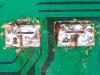
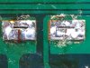
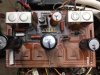
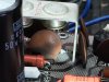
Now that they are removed, I'm becoming more and more curious as to WHY the left part of this board is discolored along with the left side of the 6-pin molex connector (pic below). It seems to me that this concern warrants some additional consideration as it could be the result of why the receiver wasn't performing properly, and therefore should be investigated to ensure there is no need to return to this board once restoration is completed. This board contains ceramic capacitors (103P77 - which I believe are .01uf ) and the one just under the rectifier diode closest to the AC inputs, and super close to the 10ohm wire round resistor, is heated pretty well (pic attached). I think these caps need to be tested and possibly replaced for good measure unless someone can tell my why, only this part of the board is showing signs of heating. I personally believe a component went bad and have caused an increase in current flow to other components, resulting in this overheating - I would love to know what's happened here so that I can properly repair. Accepting all input and advice!
The new 6-pin molex terminal will arrive today and I can't wait to see if it's a proper match!! Fingers crossed!

Oilmaster
Sonycus Peritum
Now that they are removed, I'm becoming more and more curious as to WHY the left part of this board is discolored along with the left side of the 6-pin molex connector (pic below). It seems to me that this concern warrants some additional consideration as it could be the result of why the receiver wasn't performing properly, and therefore should be investigated to ensure there is no need to return to this board once restoration is completed. This board contains ceramic capacitors (103P77 - which I believe are .01uf ) and the one just under the rectifier diode closest to the AC inputs, and super close to the 10ohm wire round resistor, is heated pretty well (pic attached). I think these caps need to be tested and possibly replaced for good measure unless someone can tell my why, only this part of the board is showing signs of heating. I personally believe a component went bad and have caused an increase in current flow to other components, resulting in this overheating - I would love to know what's happened here so that I can properly repair. Accepting all input and advice!
Welcome to the fried CR-1020/CR-2020 owners club

Hereby a link to a posting I did in another thread:
http://audiokarma.org/forums/index....-41vdc-on-outputs.787761/page-3#post-10992603
It are those 4 nasty power resistors used for voltage regulation (stone-age method) while locking them up in a confined space
LFazio51
Active Member
Hereby a link to a posting I did in another thread:
WOW! Great info and very very much appreciated Oilmaster! I will peruse it thoroughly before proceeding.
I just realized, after watching a YouTube video, that I cannot use the resistor values in the SB for the 2020 because they are recommending 33ohm 3.25wt and the 1020 uses 10ohms - the 33's will be arriving today so I guess I'll have to reorder 10ohm 3.25wt - correct? Or should I go a little higher with 5wt?
It also looks like you replaced the ceramics as well, hopefully those values are listed in your thread, if not, maybe you could point me in the correct direction?
And as Avionic said, those are some very nice photos in your thread! Thanks again to ALL who have taken the time to help this Newbie out - it's far more appreciated than you realize, and FUN TOO!