• The move to the new server is done. There are some software and database maintenance updates in process. This has us passing the hat around to help out. We appreciate any donations. Seriously, even a dollar helps. The payment page may be found here - https://www.audiokarma.org/support.html

CR1020 Restoration Guidance

You are welcome.

I am not sure where you got 10 ohm values from, but my CR-1020 manual circuit diagram shows:
R801/802: 33 ohm (mouser 588-93J33RE)
FR801/802: 22 ohm (mouser 588-93J22RE)

Euh no.... I wouldn't use 10 ohms instead, because that would raise the power rail voltage, perhaps even above the 50V rating of C805/806. In fact, it might even overload the other resistors.

I changed R803/804 from 4.7K to 10K to lower the heat dissipation (keeping things cooler in this overheated region). Those resistors are so-called 'bleed resistors' to discharge the 18,000uF capacitors after the unit is switched off, and by no means they have to be 4.7k. They stay MUCH cooler now. Those are Vishay CPF3 (3W, metal film, mouser 71-CPF310K000FHB14)
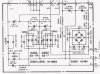
CR-1020 PSU Cap Board Small.jpg

edit: there is a 10 ohm resistor (fusible resistor FR803), but that one is not subject of the SB !
 
Last edited:
I guess I'll have to reorder 10ohm 3.25wt - correct? Or should I go a little higher with 5wt?
Not no,but hell no!... Never up the wattage on a fusible resistor. .That would be like using a 5 amp fuse in place of a 1 amp fuse
. As oilmaster has already stated. That 10 Ω fusible resistor your speaking of is not part of the service bulletin.
 
The only 10Ω resistor on that board is a fusible ( 10Ω @ 220ma ) . Don't use anything larger than and 1/2 watt resistor with a flame resist/flame proof coating.
 
The only 10Ω resistor on that board is a fusible ( 10Ω @ 220ma ) . Don't use anything larger than and 1/2 watt resistor with a flame resist/flame proof coating.

As Avionic says!
I used: Mouser 603-FRM-50JT-52-10R

Note the "end of life" message..... this stuff fades out gradually.
I hardly order anything in less than 100pcs these days (I am not saying you should, but aiming at others who rebuild/repair stuff continuously)
 
I ordered 200...When I first saw that " end of life" message.

Talking about it...... Nichicon has decided to stop production of the FG caps for all values under 1uF.
So I bought all those values in 200pcs each, for 50V and 100V version.
And while ordering anyway....did the same for anything up to 22uF
Saves a lot of ordering stress for each new project, and price per piece drops dramatically as well.
 
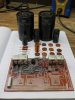
Ok, lots of great info and lots for me to digest so I'll take this one step at a time. It appears that from everyone's comments, I'm misunderstanding either the component markings currently installed OR, the Service Bulliten, therefore, I need to understand where I'm going wrong. I prepared the attached pic which illustrates the board and SB together. Hopefully it will help you guys help me acquire some "clarity" and ensure I have the correct replacement components for the SB and am installing them in the correct locations. (BTW - I just received both the 33ohm and 22ohm resistors). When I'm looking at both the board and SB, it appears to me that R801/802 are the orange/red colored wire wound resistors highlighted in yellow - if so, the markings on those are 10ohms? I'm not sure of what the markings on the fuse resistors currently installed (highlighted in blue) mean but based on the board and SB, I'm of the opinion that the 22ohm/150ma resistors should replace those marked in blue?
 

Attachments

Your attachment is correctly identifying the parts:

R801/802 are the orange red resistors (which are to be 33 ohm)
FR801/802 are the white resistors you marked blue (which are to be 22 ohm)

Now, those white Micron67 resistors have a nasty variation on which not the value but the part number is printed, so perhaps you read something '10' but they shall not be 10 ohm.

As you can see in my photos, I moved all of them to the other side of the boards, avoiding as well that they are too close to each other

EDIT; I mixed up things, I see know where your confusion comes from regarding the red resistors; that is plane wrong (perhaps off-factory or by repair technician)
 
Last edited:
Correct.

I don't know what went wrong in your unit, but those red resistors shall not be 10 ohm !
They shall be 33 ohm !
 
Last edited:
Now, those white Micron67 resistors have a nasty variation on which not the value but the part number is printed, so perhaps you read something '10' but they shall not be 10 ohm.

Here's are some better pics of them:
IMG_0403.JPG

IMG_0404.JPG
The two that are situated in the middle of the board that are supposed to be replaced with the 22ohm 3.25wt resistors are marked "HW20422 Micron 76."

The one at the edge of the board in the middle (closest to the transformer) is marked "HW20410 Micron 77."

IMG_0398.JPG

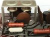
Below is a better view of the left rectifier diodes and it offers a clear view into the small ceramic caps; they look really "tired!" lol!
IMG_0406.JPG

Also, if you look at the first pic you can see where the base of the 6-pin header that the main power supply board connects, is broken and the pin is gone. I was able to source a new header from Mouser (Molex Part No. 26-20-2061 - pic below). And while I've not yet soldered it in, I have inserted it into the power supply and it's a nice snug fit! Hopefully I can get it soldered in properly and solve this problem! Maybe this info will help someone, and allow me to give back a little something in this thread since I'm the one ALWAYS "sucking-up" information here!!

IMG_0391.JPG
https://www.mouser.com/ProductDetai...=/ha2pyFaduhUxSXP7tedHYiK0m2udl7zVMUOhK5sMco=
 
Last edited:
Nice photos..I'll have to remember that part #.

Thank you! I'll provide more feedback once I install it. Hopefully the adhesive on the original 6-pin base won't be too difficult to remove. Once removed I'll glue the other in place and solder. At least I know for sure that the other board connects nice and tight! :)
 
Most of the adhesive will come off with the old connector likely.
 
Thank you! I'll provide more feedback once I install it. Hopefully the adhesive on the original 6-pin base won't be too difficult to remove. Once removed I'll glue the other in place and solder. At least I know for sure that the other board connects nice and tight! :)

Like Avionic, this Molex connector is a new option to me that I have to file.
First off or not; we all bring something :)
Nice photos indeed.
 
Below is a better view of the left rectifier diodes and it offers a clear view into the small ceramic caps; they look really "tired!" lol!

Those ceramic disc caps got dirty/discolored by the hot air coming off the power resistors that are subject of the SB.
I tested all of them on a capacitor test bench and they are hardly impacted by aging or heat exposure, so replacement is rarely required.
Just some overall board cleaning with a domestic detergent will do.

For those who wish to put new ones in, Mouser part # 594-S103M47Z5UN63L0R will do fine. They are also used on the power amp PCB.
While avoiding another capacitor dispute battlefield, for those who wish to change to polypropylene caps, Mouser part # 667-ECW-F6103JL will do fine.
I used Xicon MPP caps, but those are now obsolete...

Modern sub for the bridge rectifier D801 (and D713 on the PSU ctrl board) is Vishay 2W01G (Mouser # 625-2W01G-E4), and Vishay UF4003 (Mouser # 512-UF4003) for diodes D804/806.

I am not suggesting you should replace more parts, but some folks might like to have those references.
 
What a "wealth" of information - can I send you guys and apple pie for Christmas? ...as I can't express how much I appreciate everyone's support and help!! Especially given this is my first project.

Capacitor and Diode Data:
Thanks so much for the reference data, it will prove invaluable. These boards appear to have a rather extensive amount of work needed for a "Newbie," therefore, given the extent of this "tear-down," and my desire to NOT have to tear-down again, I think it's best to replace whatever might need replacing NOW in order to eliminate future re-entry. That's specifically why I'm so appreciative of this data as there is absolutely NO WAY I could have crossed-referenced all of this in any kind of reasonable time-frame. So, I'll look into these ceramic replacements as Oilmaster indicates along with the diodes. I think this gives me the best chance to eliminate the potential need to return to service down the road.

I'd like to wish everyone a very pleasant and productive weekend. I will be leaving shortly for a wedding in west Texas and won't be on-line very much or getting much work done. Thanks again for everything!
 
Alright, finally allocated some bench time today and made a little progress removing components and cleaning-up the board. Below is an evaluation of the results along with photos. It became clear that the maturity of this pcb and pads would require a very delicate approach so I adjusted the soldering iron to 630*F in an effort to minimize damage, however, I lost (1) pad immediately as the solder joint was cold and the pad was separated prior to my heating, and another by accident while cleaning (rookie mistake! :mad:) I have a plan for the pad that was already separated (will share once I update with component installation) and hopefully I can get a reasonable amount of solder on the one I "peeled-back" while cleaning.
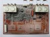
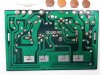
E.Cap Board - Component Removal
Board Condition: Mature with heating deformations visible
Skill Level: Beginner/Novice
Removal Results: B
Components Removed: Electrolytic & ceramic capacitors / Resistors & Fuseable Resistors

CIG_IMG003.jpg CIG_IMG004.jpg CIG_IMG009.jpg CIG_IMG011.jpg
 

Attachments

  • CIG_IMG003.jpg
    CIG_IMG003.jpg
    61.3 KB · Views: 19
Back
Top Bottom