• The move to the new server is done. There are some software and database maintenance updates in process. This has us passing the hat around to help out. We appreciate any donations. Seriously, even a dollar helps. The payment page may be found here - https://www.audiokarma.org/support.html

Crosley car radio or “what am I supposed to do with this?”

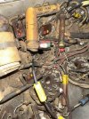
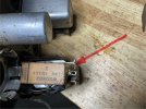
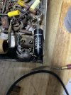
I finally found the parts list and apparently it's a thermal condenser. I have yet to find any info on the web though. I guess my Google-Fu is not as strong as I thought. Unfortunately, the parts list does not give any values or other information other than to label it as such. The term “condenser” is apparently interchangeable with “capacitor” which would lead me to expect a capacitance value and as far as I can tell, there is nothing written on it.
 
Last edited:
#14 or a chemical temperature compensating condensor to prevent station drift. or a capacitor of some kind. https://www.tubesandmore.com/schematics/crosley-corp/a459
The condensor measures 0.42pf for what it’s worth. Nothing else measures within specs so I don't expect that to be accurate, though the Surplus Sales site does sell a 0.5pf one. In terms of just getting the radio working (wishful thinking), I’m pretty sure I can do without it for the moment.
 
Would these make a good substitute for a molded mica capacitor? I am unable to find the required values otherwise And these ones are quite affordable.


IMG_0137.png
 
Silver-mica or C0G ceramics are the usual choice for this sort of thing. They don't drift with temperature. If it had mica originally, replace with another mica.

that said I'd only change them if they are causing a problem. They are pretty reliable. I've only replaced a handful that actually failed or went off value. Probably done more because the leads got broken.
 
Silver-mica or C0G ceramics are the usual choice for this sort of thing. They don't drift with temperature. If it had mica originally, replace with another mica. that said I'd only change them if they are causing a problem. They are pretty reliable. I've only replaced a handful that actually failed or went off value. Probably done more because the leads got broken.
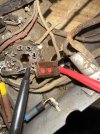
that’s what I thought but the colour codes on the mica caps in the radio do not necessarily correspond to those in the schematic. It calls for two 0.0005mf, two 0.0001mf and one 0.00025mf. Unless I’m reading the colour codes wrong, I have two 0.0002mf, one 0.0001mf and two 0.0003 or 0.0004 depending on wether it's yellow or orange. The one I have checked so far is the 0.0002 which measures at the very low end of acceptable. Also, from the looks of some of the solder joints several of them may have been replaced in the past.
it doesn’t look like it from the picture but I have lifted one leg of the cap. If the others measure somewhat close to the colour code specs, Should I just leave them as is?

IMG_1787.jpegIMG_1789.jpegIMG_1790.jpegIMG_1788.jpeg
 
Pretty fair bet it was working with those caps installed, so unless it doesn't work I'd let it be. Small value mica is usually involved in a tuned circuit so changing them forces a re-alignment.

I'd be more concerned with the old carbon resistors. Most are 20% tolerace though so as long as its somewhere near there its likely acceptable.
 
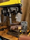
While waiting for the fiddly bits to arrive, I decided to attack the rusted mess that is the housing. Not having a bench grinder, I used the next best thing which was my drill press. It took hours to clean the first two pieces and though I couldn't get rid of all the pitting, it was well worth the time. I chose a hammertone paint which was as close as I could come to the original colour. I think it came out rather well.

IMG_1805.jpegIMG_1795.jpegIMG_1807.jpegIMG_1809.jpeg
 
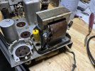
This radio is kicking my butt though I’m not about to give up. It's personal now. Trying to trace wires through the filth is proving to be quite difficult as they are so dirty that making out the colours is impossible. I decided against stripping the radio down to the chassis in order to clean it as I doubt very much I would be able to put it back together correctly. I just don’t understand enough yet to be able to do that, so I’m cleaning as I go. I’m working on the power supply at the moment.

An interesting shaped blown-out cap which measures very bad at 2.2 mf. Replaced with a 0.47 cap I had on hand.
IMG_0138.jpegIMG_0140.jpeg

It certainly looks like someone was in here before me. Unless I‘m completely mistaken, that 0.006 mf cap should be a 0.1 mf cap.
I’m going to have to make another parts order as I don't have most of the resistor values called for.

IMG_0143.pngIMG_0141.jpegIMG_0142.jpeg


Does anyone know what Ins, as in 1/4 Watt Ins, stands for? I get WW (wire wound) and carb (carbon comp) but not Ins and my Google-fu has failed me.

IMG_0144.png
 
Last edited:
The buffer cap is item 16 on the schematic. 0.0005 isn't unreasonable but sometimes those got tweaked one way or the other. Somewhere I have a book that actually has scope shots showing exactly what the output of the vibrator ought to look like along with what it looks like if the cap is too large or too small. Its possible someone tuned it that way, or its just what was on hand and deemed "close enough", which was extremely common. The buffer caps often failed and would kill the vibrator, so it was common practice to replace both together.

That big flat paper cap is a noise suppressor across the two ends of the transformer. It gets a lot of abuse too. I think thats the one shown as 0.1uf on the schematic.

not sure on the "INS", can you show me what one looks like in place? Most resistors in these old things are just common carbon type, don't believe I've run into one marked "INS".
 
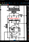
Is this a correct description of what is happening here? The 6 volts DC from the battery are fed into the Vibrator which turns it into a close approximation of AC by creating a square wave as the “clapper” switches back and forth between the two terminals. This is required because AC can easily be boosted whereas DC cannot. It then goes through what looks for all the world like a fixed bias circuit and into the primary windings of the transformer. The voltage is transferred across to the secondary windings by induction and is amplified by the winding ratio between both sides. It then goes to the rectifier where it is converted back to DC, but at a much higher voltage.


IMG_0148.png
 
yep, vibrator gives square-ish waves. Into the transformer for a step-up, on to the rectifier to make high voltage DC. That whole side of the transformer is just like any regular tube gear, plus maybe an extra cap to filter out high frequency trash that wouldn't exist on a mains fed supply.

Its only connected on one side of the transformer primary at a time though. The resistors from end to center tap are there to reduce transformer flyback effects which produce a lot of noise and voltage which would abuse the vibrator contacts. A normal AC feed has the entire primary and swings it positive to negative, this just alternates which side is connected to positive.


If you really want a head trip, look up synchronous vibrators. Those switch the secondary side along with the primary, causing the positive side of the high voltage DC supply to always be connected to the transformer lead that is outputting positive voltage. It ends up basically being a mechanical rectifier, eliminating the need for a standard one.
 
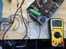
After ruining the Vibrator through what I can only ascribe to stupidity, I had to come-up with another way to get a 6vac supply to the transformer. I dug up a cheap 120/6-0-6 transformer and hooked it up to the primary side of the radio's PTO. The filament transformer actually puts out 7.16 volts rather than 6v with wall voltage with a corresponding 204.7 volts at the secondary measured from one side of the secondary and chassis ground giving a winding ratio of 28.58:1. From what I have been able to glean from the internet, I should be seeing something between 100v and 150v. If I drop the voltage from my variac to 100v in order to get a 6volt output, I still read over 170v at the secondary.

IMG_0154.jpeg
IMG_0155.jpeg

It's something of a Rube Goldberg setup but will at least allow me to carry on until such time as I figure out what I did to fry the vibrator.
Oh, and the on/off- volume pot has an intermittent fault and will only occasionally pass current but when it does work, I get 5.9 vdc at the fillaments. So there is that.
 
Is that voltage being read in an open-circuit condition, or with the tubes installed and operating? It is common for typical circuit voltage levels to be published with the unit assembled and operating at a particular power level, audio output, etc.

 
Is that voltage being read in an open-circuit condition, or with the tubes installed and operating? It is common for typical circuit voltage levels to be published with the unit assembled and operating at a particular power level, audio output, etc.
Those readings were taken with no tubes in. The schematic calls for 256 volts at the plates and 240 at the cathode of the 6X5 rectifier. That will be my next step, I think
 
unloaded its going to be high but its somewhere in the realm of sanity.

feeding it 6vac from a step-down will be cleaner power, but the different wave shape may result in somewhat different DC voltages. I wouldn't get too picky about it being dead on, it just needs to be somewhere in the realm of sanity. Under 280 at the output tube plates is probably just fine.
 
Back
Top Bottom