• The move to the new server is done. There are some software and database maintenance updates in process. This has us passing the hat around to help out. We appreciate any donations. Seriously, even a dollar helps. The payment page may be found here - https://www.audiokarma.org/support.html

Crosley car radio or “what am I supposed to do with this?”

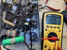
I plugged in the 6X5 rectifier and checked the voltages. After about 10 minutes of gradual increase, the plate voltages settled at 198 volts AC at the plates and - 246 volts DC at the cathode. Once I had remembered that this was a positive ground circuit, I compared the voltages to what the schematic says I should expect. The cathode voltage was quite close but the plate voltages were low. 198 volts versus the 256 volts expected which is well outside of the 10% variance stated to be expected. These measurements were taken with only the rectifier tube in circuit and all measurements taken measured to chassis ground. There also seems to be a slight voltage drop across the pilot light of 0.4 volts and a draw of 0.8 amps (I was reading 0.3 previously) to the heaters. I get 5.9 volts at all the heaters if I hook the 6 volt supply directly to any one of the tube sockets and 5.6 when measured through the on/off switch and pilot light with power applied to the chassis and negative voltage supply.
I find the correct cathode voltage reading particularly interesting as it is a function of the plate dissipation.
perhaps things will change as I replace more of the out of spec components.
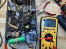
IMG_0159.pngIMG_0158.jpegIMG_0157.jpeg
 
I agree. Whatever job they were supposed to be doing, they've long retired from and moved to Del Boca Vista Stage II
That’s in So-Cal, right? :p

My intent was just to make sure that the transformer was still good, which it would seem to be
I have an order in for the rest of the caps which should show up in a few days. Anything from Mouser takes several weeks to get here. In the mean time, I have some orange drop caps that should do the trick in a couple of places.

thanks for the help. It is much appreciated.
 
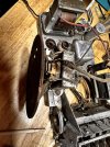
Well shoot! When I first disassembled the radio, I didn't notice that this wire was disconnected from the output transformer.
Is it worth trying to take the PTO apart to try and reconnect the two wires? Given its current unusable state, I figure I have nothing to lose. Considering the condition of the speaker itself, I was only going to use it to see if I could get any sound out of it at all once the restoration was complete. I was originally thinking of just replacing the speaker itself so as not to have to find another transformer with similar impedances. As far a finding a complete replacement, I am limited to a 5 inch by 2 inch tall speaker basket.
IMG_1823.jpegIMG_1828.jpeg
 
might not be as difficult as I had thought. This is almost exactly the same transformer as I have.


Well, that dream didn’t last long. I was able to reconnect one lead but the other was so short I could hardly see it, let alone solder to it. 2020_0729_205121_005.jpeg
looks like I’m looking for one of these.
2020_0729_210722_005.jpeg
 
A quick capacitor question.

In a “normal” circuit, the negative side of a cap is tied to ground with the positive side attracting electrons and thus building up a charge. Reversing this will cause a short and the current to rise sharply and potentially blow up the cap. Logic would dictate tying the positive side to ground in order to follow the polarity of the circuit but at the same time, would this not cancel the filtering or suppressing or storage function of the cap as the charge would build up on the wrong side of the path? Conversely, would tying the positive terminals to positive ground allow the caps to function as intended since the charge would build-up on the correct side of the dielectric.
This is hurting my brain. I’ve been reading up on the theory of capacitance for over an hour now and I’m no smarter than I was when I started.
 
Last edited:
What output tube does it use? Probably not going to find that specific transformer but you can likely find something that will sub with minimal fuss.


The 6v polarity doesn't honestly matter here. the transformer isolates all that, so the plate supply will be positive relative to chassis ground, even if the chassis is positive relative to battery negative. The filter caps have to be negative to ground or they will be charged in reverse and smoke will come out of them. If there aren't any electrolytic caps on the 6v circuit you could honestly flip the 6v polarity without it caring. The mechanical vibrator won't be bothered, but a solid state vibrator absolutely won't like that. The tube heaters and pilot light aren't polarity sensitive.

there are cases where positive goes to chassis ground, but basically thats for bias supplies that will measure negative relative to ground. Seriously doubt this is fixed bias so it wouldn't have any of that.
 
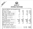
The tube is a 6K6 in a single ended configuration with a stated plate voltage of 220v. The speaker has a stated impedance of 4.9 ohms. Not being able to measure the winding ratio, I can only go by what I can find online. It seems that a transformer with an impedance of 8k should work and since I will have to replace the speaker anyway, I can choose a speaker whose impedance will best match the transformer and tube.

IMG_0165.png
 
Last edited:
yea 8K sounds about right based on datasheet. Secondary is just whatever you want for the speaker, if you can get one with a 4 and 8 ohm tap it'll run anything commonly available.

Not sure if 8k single ended is a commonly available transformer, but old "universal" transformers can be had and wired to cover that sort of load. Either way I wouldn't spend a pile on it, the fidelity isn't going to be amazing and it doesn't warrant a fancy transformer to get there.

1747339488763.png
 
yea 8K sounds about right based on datasheet. Secondary is just whatever you want for the speaker, if you can get one with a 4 and 8 ohm tap it'll run anything commonly available.

Not sure if 8k single ended is a commonly available transformer, but old "universal" transformers can be had and wired to cover that sort of load. Either way I wouldn't spend a pile on it, the fidelity isn't going to be amazing and it doesn't warrant a fancy transformer to get there.

View attachment 3504082
I found a transformer on eBay for 15 bucks which should do the trick. With a winding ratio of 35:1, it should give me an impedance of 9800 ohms Into an 8 ohm speaker. (35x35)x8 ohms = 9800 ohms. 4900 into a 4 ohm load.
 
That should do it - if the size won't work, PM me, as I have a box of salvaged SE transformers - should have something that will fit.
 
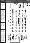
20 Meg or 20K? the schematic calls for a 20 MegOhm resistor and the parts list calls for a 20 KOhm. Is the purpose of this resistor to protect the oscillator grid by shunting to ground any current spike piked-up by the antenna? If that’s the case then 20Meg would seem make sense.


IMG_0170.jpegIMG_0167.jpeg
 
'M' was used for thousand (M = Roman numeral 1000) by some instead of 'K'. 20K is about right for oscillator grid return.
 
That makes sense since K means Kilo.
I have replaced all the resistors and caps excluding the mica ones and I’m waiting on a replacement transformer which will take a week or two. In the mean time, I have put power to the radio and measured the voltages. Below are the voltages I got from the 6X5. I tried three different ones including the original Crosley branded metal tube one and got these results to within a couple of 10ths of a volt. All three tubes tested good with the original one testing slightly better. These voltages were taken without the output transformer and speaker. That may account for the slightly higher cathode voltage but not the much lower than expected values on the plates. I get basically zero volts on the other tubes. The Plates on the rectifier are directly connected to each end of the secondary windings which could indicate a problem with the transformer but does not explain the high voltage on the cathode (still within the stated 10% expected range). I have a bit or reading to do between now and the arrival of the transformer.

image.jpg
 
Last edited:
No output transformer means no supply to the output tube, and no current load. I'd expect high DC output voltage under those conditions.

Don't run it with no plate supply to the output tube, the screen will try to be the plate and it will vaporize. Hopefully it hasn't already.
 
No output transformer means no supply to the output tube, and no current load. I'd expect high DC output voltage under those conditions.

Don't run it with no plate supply to the output tube, the screen will try to be the plate and it will vaporize. Hopefully it hasn't already.
Good to know. Fortunately I only ran it for about 30 seconds at a time. I tested all the tubes last evening and they all test fine.
I will be doing some reading over the next few days in an attempt to educate myself further.
 
Last edited:
Back
Top Bottom