• The move to the new server is done. There are some software and database maintenance updates in process. This has us passing the hat around to help out. We appreciate any donations. Seriously, even a dollar helps. The payment page may be found here - https://www.audiokarma.org/support.html

CROSSOVER CAPACITOR QUESTION ?

Rex Runner

Tobes of Hades lit by flickering torchlight
Subscriber
4F4B21DF-9371-4BE5-BBE8-7A61C98C5DE2.jpeg Proud owner of a mint pair of Boston Acoustics A150
One day I felt the need to add a little heat while listening to a Rush song
Hooked up to a restored 2235 I maybe hit 12 o,clock and heard a tweeter blow
Crap I thought. Maybe pushing 15 watts? What the hell
I pulled the tweet and it ohmed out fine
Straight to the crossover I went
My question is...
All caps are metal can bi polar except the one I have pictured
What exactly are these yellow caps?
 
Register to hide this ad
Looks like a 3.3uF 100V mylar film cap.
Check for a cold solder joint or failed resistor.
Film caps do not commonly fail but there are always exceptions.
Check crimped connections, they can corrode and go high resistance.
 
I think my main question is the rest of the capacitors are all non polarized electrolytics and a single film cap?
My tweeter came back to life when I replaced the film cap with a non polar lytic
Speakers are definitely worthy of a full recap
Just wonder if the film cap is a weak link?
 
No, a tweeter should never see 100V and films are just as durable as NPEs. More, in fact, as they don't dry out.

Besides the film sounds better on mids and tweeters, and are still inexpensive in those sizes.

Finally, NPEs tend to have higher resistance so the voicing of the speaker can change a bit if you switch types.
 
I haven’t been in the hobby as long as many members here
Maybe 60 different pair over the last couple years
Almost all had the non polar lytics and the real old ones were a hard plastic
This is the 1st time I lost a capacitor in a dividing network
I have upgraded a few with better more expensive caps but was mildly disappointed with the results
My outlook on crossover,s now....
If it ain’t broke, don’t fix it
 
BA used film on the tweeter because that is where it makes the most sense,
and if an NPE ages to become leaky it could take out a tweeter. I'd put a film
back in there and recap both speakers.
 
That is the game plan
I put in a replacement just to see if it was that cap
Making a BOM this weekend for a complete recap
 
I haven’t been in the hobby as long as many members here
Maybe 60 different pair over the last couple years
Almost all had the non polar lytics and the real old ones were a hard plastic
This is the 1st time I lost a capacitor in a dividing network
I have upgraded a few with better more expensive caps but was mildly disappointed with the results
My outlook on crossover,s now....
If it ain’t broke, don’t fix it

I hear ya. Sometimes swapping cap types can drastically alter the character of a speaker. :(

If you decide to go all poly, Clarity CSA series sound very close to electrolytic in my experience. Have only recapped with them once, but am more than happy with the result (I used the 250v version). No harsh brightness that some polys bring, just good clear sound.

If sticking with electrolytic, Mundorf E-Caps are a great choice there, as long as you don’t need over 50v.

Joe
 
I hear ya. Sometimes swapping cap types can drastically alter the character of a speaker. :(

If you decide to go all poly, Clarity CSA series sound very close to electrolytic in my experience. Have only recapped with them once, but am more than happy with the result (I used the 250v version). No harsh brightness that some polys bring, just good clear sound.

If sticking with electrolytic, Mundorf E-Caps are a great choice there, as long as you don’t need over 50v.

Joe

My experiences too. ClarityCaps have a warm tone. ESR similar to electrolytics, so they sound good on vintage speakers. Plus, Mundorf E-Caps are great. A quality NPE.
 
This is culled from a variety of writeups on electrolytic capacitors I elsewhere posted, slightly edited for content, to remove tangential material, and for greater brevity, but the subject is complex and I refer you to the primary sources and manufacturer literature. I forsee yet another debacle about capacitors, ending in a smoking ruin of locked thread. I am putting down the capacitor analysis, and backing away. You may verify all of this from manufacturer literature and engineering texts.

For those interested in technical discussions on the subject, Cyril Bateman's excellent work on capacitors is a good source for actual measurements of capacitors in audio, and he understood how to do proper measurements using low-distortion audio sources. Bateman truly was The Man when it came to capacitors in audio. Steve Bench did actual experiments and includes Lissajous plots. Again, research and take your own counsel.

Regardless of the electrolyte type, electrolytic capacitors have abysmal performance across the board, but offer a price and density point not otherwise achievable. That is their sole virtue. The cause for the poor performance of electrolytic capacitors arises from the slow speed of charge migration (below detailed), an effect which is poorly understood by hobbyists, and even by many electrical engineers. Analog engineers, however, well understand it because it breaks circuits.

View electrolytic capacitors with substantial suspicion, like a cat noticing their human removing the cat carrier from the closet. Nothing good comes of using them.

Poor Performance Arising from Ion-Movement and Formation of Oxide Layer

Capacitance is a function of plate area, and this ultimately controls the physical size of the device. An electrolytic capacitor increases plate size by etching the plate, greatly increasing its surface area without increasing its physical area. The etched plate is then coated with an electrolyte to migrate into the etched region, because the etching would otherwise decrease the distance from the opposing plate. The electrolytic capacitor therefore relies upon ion movement in the electrolyte to match charge distribution upon the plate, in a one-for-one relationship. Ion movement is, of course, quite slow, which is the inherent limitation and the cause of poor performance (below explained) in electrolytic capacitors beginning at approximately 1k Hz, and rapidly falling off above that point. But even ripple current at 50/60 Hz or 100/120 Hz, depending upon rectifier configuration, is not well filtered because of the slowness of ion movement. This is why power supplies decouple the capacitors to improve performance, i.e. filtering at higher frequencies.

Electrolytic capacitors may be "wet" or "dry", both terms referring to the type of electrolyte used. Non-solid (wet or liquid electrolyte) electrolytic capacitors typically use boric acid or another acid. Solid electrolytes, however, do exist, and conductive polymers are now commonly used for SMD applications. While solid electrolytes have substantially greater lifespan — no liquid to evaporate, so the lifespan increases in certain applications from as little as a few years to as much as twenty — the plastics are vulnerable to heat, including assembly soldering, and the capacitors have significantly poorer tolerance for voltage spikes which may over time result in premature failures that would not occur with wet electrolytes.

The natural expectation, mistakenly applying properties for an ideal device to actual devices, is that charge instantly distributes at the speed of light because this is how fast electrons move. This is incorrect. Charge is moving through the circuit from one side of the capacitor to the other, dipoles must align, electrons must diffuse in/out of the dielectric, and charge must distribute across the plate. Much happens that is not ideal, particularly with electrolytic capacitors, again given the limitations of ion movement.

So the frequency-dependent behavior is not the only issue shifting corner frequencies for filters. The corresponding issue is that the capacitance-value tolerance for electrolytic capacitors is quite poor, as the industry-published value tolerances are typically in the range –20% to +80% from the stated value, with the nominal capacitance being some sort of bogey at a particular frequency, usually measured at or below 1k Hz. This was far worse in Ye Olden Times, so the original cans were not necessarily the specified values.

Degraded Performance versus Frequency

The performance falloff with frequency can be considerable.

Here is what Cornell-Dubilier has published on frequency effects:
http://www.cde.com/resources/catalogs/AEappGUIDE.pdf

Aluminum Electrolytic Capacitor Application Guide
Cornell-Dublier

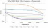
Above a certain temperature-dependent frequency, the capacitance drops rapidly with increasing frequency. This behavior is most dramatic at very cold temperatures and is related to the distributed RC nature of the electrolyte-filled etch tunnels, and also to the viscosity of the electrolyte, which directly affects its ionic conductivity. See Figure 6 for a typical plot of Cs versus frequency and temperature.


Capacitance vs. Frequency - Aluminum Electrolytic Capacitor Application Guide - Cornell-Dubilier.png
Capacitance versus Frequency​

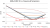
In all cases the ESR decreases monotonically with increasing frequency until the onset of skin effect of the metallic components, typically at 100 kHz or greater. Figure 7 shows typical behavior of Rs versus frequency and temperature.

ESR vs. Frequency - Aluminum Electrolytic Capacitor Application Guide - Cornell-Dubilier.png​

ESR versus Frequency
​
Cs, Rs and Ls together with their variations with frequency and temperature impart a device input impedance magnitude seen in Figure 9. At low frequency the capacitive reactance dominates, and at very high frequency the inductive reactance dominates. In between, the reactances fully or partially offset each other, and Rs constitutes the main component of the impedance. At the self-resonant frequency (SRF) the impedance magnitude and ESR curves touch, as seen in the figure.

Impedance vs. Frequency - Aluminum Electrolytic Capacitor Application Guide - Cornell-Dubilier.png
Impedance versus Frequency
​
Electrochemical Formation of Dielectric Using Oxidation

The dielectric in an electrolytic capacitor is constructed via electrochemistry, essentially anodizing — selectively oxidizing or corroding — the aluminum surface, and the result therefore consists of various oxidation states of aluminum oxide. Therein lies the problem. The main oxide of interest is Al2O3. (For this discussion I'm neglecting tantalum oxides and similar specialty dielectrics, although these similarly function. Left as an exercise for the reader.) The reverse of the forming process occurs when the dielectric is run in the reverse direction, and reduces the dielectric to base metal. The ultimate result is dielectric failure. Such an outcome is precisely why electrolytic capacitors used in the reverse direction, i.e. miswired or with AC sources, explode as the insulator breaks down and current boils the electrolyte.

The effect of dielectric damage from reverse current has implications for non-polar electrolytics, and at a later point is discussed.

Semiconductor and Rectification Effects from the Oxide Layer

The semiconductor properties of Al2O3 are well known, such that, more or less, when Al2O3 has a surplus of aluminum it acts is an N-type semiconductor and when it has a surplus of oxygen it is a P-type semiconductor. Like other semiconductors, creating a junction of metal oxide and metal creates a rectifier, i.e. unidirectional current flow, often with minor leakage current in the reverse direction, since the metal oxides are imperfect by way of the forming process and structural defects, although modern manufacturing techniques have created great uniformity. I note that Georgiev's work from 1945 on the subject of rectification remains accurate, of course, but the confusion of that era over semiconductor effects versus dielectric porosity has, to some extent, been resolved, particularly with respect to dielectric absorption, aka soakage. So the explanations of semiconductor and other effects set forth in the older books are often very dated from a scientific and engineering perspective, and should not be relied upon without confirmation. As an aside, aluminum oxide rectifiers remain suitable for very high voltages and continue to be used for such applications.

The diode effect is peculiar with unpredictable effects, because the dielectric surface is far from homogenous in any dimension, particularly given the electrochemical etching process and subsequent electrochemical anodizing, and the rectification effect is not as dependent upon the quantity (or quality) of oxide as the maximum voltage rating (a function of thickness) will be.

All of the manufacturers mention rectification effects because this is real and exists. Hobbyists often use poorly configured experiments and then decry the effect. To find the parallel diode the experiment must apply a low-voltage AC signal in both directions and then subtract to find the alteration. Voltage must be low enough that significant damage to the dielectric does not occur. Cover the capacitor in case of failure.

End of Part 1.
 
Part 2

Electrolyte Degradation Over time

The electrolyte, as above mentioned, over time degrades, typically from electrolysis of water into H2 and O2, both of which are lost. So the fact that the electrolyte is gradually declining doesn't mean that the capacitor properly or consistently functions for the entirety of its lifespan, or that its lifespan is good. Remember, the purpose of the electrolyte is ion migration to permit plate charge. If the electrolyte's ability to move ions is impaired, as occurs with increased viscosity, the capacitor won't function or it will have frequency-dependent degradation. What really matters for the longevity of a wet electrolyte is that the liquid is over time lost, both through normal evaporation and being baked out by high temperatures.

Electrolytics, by virtue of their design, are limited-lifespan devices. The seals are imperfect and the inherently higher ESR creates internal heat. Poor-quality electrolytics can fail in a few years. Well-made ones can last a decade or two, sometimes longer if properly sealed. The issue is that the properties deteriorate with age, even if the capacitor does not fail. Old capacitors have no Magickal Mojo; what they have is a death sentence which will eventually be carried out. Electrolytics cans explode when they die, hurling metal around like an IED.

The main issue beyond evaporation is that the oxide layer, essentially being anodizing, is fragile and readily dissolves back into the electrolyte during disuse. The approximate values for deterioration of a modern electrolytic capacitor in storage are normally on the order of 2^Year, and the manufacturers set forth a variety of values:
After 1st Year: drop in capacitance is about 2%, leakage increases by about 2x

After 2nd Year: drop in capacitance is about 4%, leakage increases by about 4x
​

CDE or Nichicon application notes, for example, concur with these values. Rubycon states the changes are small after two years and then increase. TDK claims longer lifespan but doesn't fully specify the changes as it varies across the product line. CDE suggests only a few years. Much of these values are likely hedging to prevent the inevitable lawsuits — particularly after the spate of lawsuits for motherboard failures in the 1990s — and to protect the manufacturer's reputation.

Storage in this context normally means sitting in a distributor's warehouse at 35 or 40 degrees C. So in a home at a lower temperature it may deteriorate less. The reactions are temperature dependent.

While having implications for the corner frequencies of filters, the drop in capacitance with time, however, is not the main issue; that issue is the increase in leakage current which, in turn, causes ohmic heating, particularly from ripple current in a power supply. After three years the capacitor is supposed to be tested for leakage, and after four reforming is mandatory. The leakage current is very small in a modern electrolytic capacitor, at least one operated within design goals, so doubling or quadrupling it is likely still small. Reforming after a few years may just be CYA, but it would not surprise me that the oxide starts to rot after that.

The reforming current is normally severely limited, something like a series resistor of 100k Ω, with a reforming time is 30 to 60 minutes depending upon the voltage rating. Something like that. The goal is prevent ohmic heating while the oxide layer rebuilds. So it cannot be reformed in an actual circuit experiencing real current. The process requires disconnecting the capacitor, using a very high-value resistor as a load to limit current, run for a bit to reform, then reconnecting to the circuit.

The degradation of the electrolytic capacitor is a well-studied issue, with mountains of technical material on the subject trivially available on the interwebs. For example, see:
Physics Based Electrolytic Capacitor Degradation Models for Prognostic Studies under Thermal Overstress
Chetan S. Kulkarni, Jose R. Celaya, Kai Goebel, and Gautam Biswas
European Conference of the Prognostics and Health Management Society, 2012

https://ti.arc.nasa.gov/publications/5005/download/

2. ELECTROLYTIC CAPACITORS

Electrolytic capacitor performance is strongly affected by its operating conditions, such as voltage, current, frequency, and ambient temperatures. [...]

A primary reason for wear out in aluminum electrolytic capacitors is due to vaporization of electrolyte (Goodman et al., 2007) and degradation of electrolyte due to ion exchange during charging/discharging (Gomez-Aleixandre et al., 1986; Ikonopisov, 1977) , which, in turn leads to a drift in the two main electrical parameters of the capacitor: (1) the equivalent series resistance (ESR), and (2) the capacitance (C). The ESR of a capacitor is the sum of the resistance due to aluminum oxide, electrolyte, spacer, and electrodes (foil, tabbing, leads, and ohmic contacts) (Hayatee, 1975; Gasperi, 1996). The health of a capacitor is often indicated by the values of these two parameters. There are certain industry standard thresholds for these parameter values, upon crossing these threshold barrier the component is considered unhealthy to be used in a system, i.e., the component has reached its end of life, and should be immediately replaced before further operations (Lahyani et al., 1998; Eliasson, 2007; Imam et al., 2005).

[A]n aluminum electrolytic capacitor, consists of a cathode aluminum foil, electrolytic paper, electrolyte, and an aluminum oxide layer on the anode foil surface, which acts as the dielectric. When in contact with the electrolyte, the oxide layer possesses an excellent forward direction insulation property (Gasperi, 1996). Together with magnified effective surface area attained by etching the foil, a high capacitance value is obtained in a small volume (Fife, 2006). Since the oxide layer has rectifying properties, a capacitor has polarity. If both the anode and cathode foils have an oxide layer, the capacitors would be bipolar. In this work, we analyze “non-solid” aluminum electrolytic capacitors in which the electrolytic paper is impregnated with liquid electrolyte. [...]

2.1. Overview of Degradation Mechanisms

The flow of current during the charge/ discharge cycle of the capacitor causes the internal temperature to rise. The heat generated is transmitted from the core to the surface of the capacitor body, but not all the heat generated can escape. The excess heat results in a rise in the internal temperature of the capacitors which causes the electrolyte to evaporate, and gradually deplete (Kulkarni, Biswas, et al., 2011b; Kulkarni, Celaya, et al., 2011). Similarly in situations where the capacitor is operating under high temperature conditions, the capacitor body is at a higher temperature than its core, the heat travels in the opposite directions from the body surface to the core of the capacitor again increasing the internal temperature causing the electrolyte to evaporate. This is explained using a first principles thermal model of heat conduction (Kulkarni, Biswas, et al., 2011b; Kulkarni, Celaya, et al., 2011).

Degradation in the oxide layer can be attributed to crystal defects that occur because of the periodic heating and cooling during the capacitor’s duty cycle, as well as stress, cracks, and installation-related damage. High electrical stress is known to accentuate the degradation of the oxide layer due to localized dielectric breakdowns on the oxide layer (Ikonopisov, 1977; Wit & Crevecoeur, 1974). These breakdowns, which accelerate the degradation, have been attributed to the duty cycle, i.e., the charge/discharge cycle during operation (Ikonopisov, 1977). Further another simultaneous phenomenon is the increase in the internal pressure (Gomez-Aleixandre et al., 1986) due to an increased rate of chemical reactions, which can again be attributed to the internal temperature increase in the capacitor. This pressure increase can ultimately lead to the capacitor popping.

All the failure/degradation phenomenon mentioned may act simultaneously based on the operating conditions of the capacitors. We first study the phenomenon qualitatively, and then discuss the steps to derive the first principles analytic degradation models for the different thermal stress condition. Electrolyte evaporations is caused either due to increase in internal core temperature or external surrounding temperature. Both phenomenon lead to the same degradation mode,caused either by the high electrical stress or thermal stress, respectively.
​

Non-Polar Electrolytic Construction

A non-polarized electrolytic capacitor is not magickal, merely being two ordinary electrolytic capacitors placed back-to-back, such that each capacitor is in series with the other but the polarities are facing in opposite directions. Charge moving in the reverse direction, from the perspective of each device, consequently travels through the electrolyte and is thus rectified, as it would in an improperly configured uni-directional electrolytic capacitor.


So as the oxide reduction from reverse current flow begins, it is far from uniform because the thinnest spots, of necessity, pass more current, and hence preferentially reduce. Such reduction eventually creates a thin spot, but it will not necessarily create uniformly greater leakage across the entire surface, and as long as the oxide is thick enough to minimize leakage at the applied voltage the layer still functions. This is key. So the capacitor will not necessarily explode from the application reverse-current , which is why a non-polar electrolytic can survive in an AC application, it merely poorly functions from a linear perspective.

The dielectric layer will, however, of necessity be damaged and have a dramatically reduce lifespan as compared to a properly configured, i.e. unidirectional current flow, electrolytic capacitor. This is why capacitors intended for long-lifespan or mission critical use are typically formed at 125% of rated voltage for general purpose use, and 200% and above. The oxide layer, of course, will over time dissolve into the electrolyte, so it is not clear how significant the benefit is.


Because the reverse-current has a lower duty cycle, in the case of symmetrical AC it would be 50%, the capacitor does not explode and has enough time to regenerate the degraded oxide. A thicker oxide layer is more robust for AC signals which gradually damage the oxide layer. The de-forming therefore only serves to shorten lifespan, not make the rectification effects more pronounced. Absent other design changes, NPEs, either in a single package or constructed from two devices, will always have shorter lifespans than electrolytics not subjected to AC currents.

Summary

To summarize, a conventional electrolytic therefore has substantial distortion because the capacitor has (a) non-linear behavior, i.e. its resistance (ESR), capacitance, and group delay all vary with frequency, (b) rectification effects, and (c) dielectric absorption which performs signal averaging. Such properties, again, are well known to analog engineers. Electrolytic DA causes odd-order harmonics and significant IM. Cyril Bateman measured harmonic distortion and IM in non-polar electrolytics and reported that good electrolytic capacitors did not match the performance of poor film capacitors, and Walt Jung also did some work on the subject.

Aside from situations requiring higher values at lower price points, where NPE is really the only practical option, no good reason exists to ever use an electrolytic capacitor in a crossover.

Barbie says, "Electrochemistry is Hard!"
 
That is the game plan
I put in a replacement just to see if it was that cap
Making a BOM this weekend for a complete recap

I have a pair of BA 150 s that I got when an AK member put up a pair of cabinets
for free, then another member put up all the drivers and crossovers at a decent
price. Still have to recap them and put them together.
 
I think my main question is the rest of the capacitors are all non polarized electrolytics and a single film cap?
My tweeter came back to life when I replaced the film cap with a non polar lytic
Speakers are definitely worthy of a full recap
Just wonder if the film cap is a weak link?

Many classic Infinitys (maybe other brands as well?) used NPE's (non polarized electrolytics) throughout their crossovers EXCEPT for the EMIT tweeters which used the yellow poly caps.
Conventional wisdom says those yellow poly caps are the less likely to fail over time compared to the NPE's.
 
Last edited:
Many classic Infinitys (maybe other brands as well?) used NPE's (non polarized electrolytics) throughout their crossovers EXCEPT for the EMIT tweeters which used the yellow poly caps.

Sure. For the reasons I above set forth the performance at upwards of 2,500 Hz would have been horrendous with the non-polar electrolytic.

I don't know if you remember, but thirty or forty years ago the cost of film capacitors was prohibitive for most commodity uses. Still is when making a volume product where consumers don't care and won't pay more for a difference that is not understood. In the 1980s I used to salvage pickle-jar sized filter capacitors around (it's been forty years, so memory may be a bit off) 10,000 or 15,000 µF @ 50 VDC from equipment in order to build highly-regulated linear supplies (using three-terminal regulators with a pass transistor) for digital logic. At the time those capacitors were $20 apiece on the surplus market, which was real money. One could get a nice dinner for that. Those electrolytics are today worthless, of course, because of deterioration. I need to rebuild all my Altair 8800b and IMSAI 8080 which use such capacitors, and the new ones will be the size of a roll of thread.

I remember using tantalums for power supply regulators in the 1980s (before I learned about conflict minerals) and those were a few dollars apiece for values around 10 µF. This was many times the price of a conventional electrolytic, but the properties were better for high-frequency transient response with digital logic.

I may now use in a crossover either (a) a $0.60 non-polar electrolytic or (b) a $25 polypropylene capacitor (constructed from multiple smaller capacitors and fully bypassed). Guess what my choice is? Hint: it's not the distorting unit. I could never make that choice on a speaker intended to be sold in a commodity channel at a low price point. Back in the day such choices were routinely made by bean counters, not engineers, which is why we may now fix those bad decisions.

Conventional wisdom says those yellow poly caps are the least likely to fail over time.

Perfectly sensible. At room temperature, with low currents (i.e. low plate damage) and low voltage (low dielectric damage), such as those used in a crossover, polypropylene capacitors have a very, very long lifespan, typically reported by the manufacturers as > 300,000 hours. I doubt the reliability, post early failures, was much different for those capacitors versus todays devices.

Edit: fixed typo.
 
Last edited:
I have a pair of BA 150 s that I got when an AK member put up a pair of cabinets for free, then another member put up all the drivers and crossovers at a decent price. Still have to recap them and put them together.

Boston Acoustics used bypass capacitors in many of its lines because the sound was deemed improved enough to warrant the additional manufacturing expense.

That's one way to improve the performance at higher frequencies. Pure film is, of course, the best.
 
@Retrovert
I know how you feel about PET versus PP caps, but how about PET versus NPE? Seems to me like it might be a cheaper upgrade from NPE versus PP. (more expensive than NPE, but usually cheaper than PP caps).

And to me they sound somewhere in the middle also, not as bright as PP caps.
 
Polyester (polyethylene terephthalate aka PET) — Mylar is the Dupont and Teijin Film Enterprises trademarked name for polyester — has drawbacks:
(a) PET Has Profound Dielectric Absorption, which performs signal averaging. The significant difference in dielectric absorption must not be ignored. PET is 0.5% while polypropylene 0.05%, i.e. a factor of ten worse. This accounts for the sonic differences. The reason, in brief, is migration of electrons into the dielectric which are then released over time. Think of this as signal averaging as electrons are stored and over-time released. DA is a significant issue in low-noise opamps because the capacitors can integrate over time. Anyone who pushes PTFE (tradename Teflon) for interstage coupling capacitors claiming it has cleaner sound, and a dielectric absoprtion of 0.01% (that's 1/5th of PP and 1/50th of PET) might want to think about using PET instead of PP. As an aside, DA in a capacitor, including a CRT (a giant leyden jar charged to many kiloVolts), can kill you even though the leads are actually shorted and the capacitor is stored with the leads shorted. When the short is removed the dielectric relaxes, and plate-to-place electron movement may again resume.

(b) PET is Hygroscopic, and any retained moisture causes depolymerization with heat, and that heat arises from ESR which is more significant with constantly changing AC signals. .Any damage to the jacket will over time result in deterioration.

(c) PET has a Positive Temperature Coefficient which cause capacitance to rise with temperature. This is not an issue for motor-run applications, but might be for audio. Particularly given that the ESR may give rise to ohmic heating.

(d) PET has high affinity for oil, able to absorb thirty times its weight, which is three times better than cotton which can absorb roughly ten times its weight. This is why PET is used for petroleum oil spills in oceans and waterways. This has ramifications for wet capacitors, which are commonly used in high-voltage applications. Such capacitors are not recommended for audio, but a fetish for using high-voltage capacitors does exist as the larger sizes are considered to be evidence of greater sonic bliss. What happens, in fact, is the dielectric absorbs oil and thus has greater dielectirc absorption, see above.

(e) Dissipation Factor Is High and Varies With Temperature. Polypropylene is constant, whereas PET alters with temperature. PP = 0.0005, PET = 0.0050, a factor of ten greater. This means that PET heats up more than PP, causing temperature distortion and other non-linear behavior.​

The sole advantage of PET is the 50% larger dielectric constant (ε = 3.3 versus 2.2), which increases capacitance 50% per unit volume, lowering the price and reducing the physical size. PET is therefore used to create less-expensive capacitors.

Here's what Bob Pease had to say on the subject:
Troubleshooting Analog Circuits With Electronics Workbench Circuits
Robert A. Pease
1991​

The different dielectrics are their most interesting ingredients. Often a designer installs a polyester capacitor (technically, polyethylene terephthalate, often called Mylar-a trademark of E. I. DuPont de Nemours and Co.) and wonders why something in the circuit is drifting 2 or 3% as the circuit warms up. What’s drifting is probably the polyester capacitor; its TC of 600 to 900 ppm/OC is 10 times as high as that of a metal-film resistor.​

Aside from hitting a lower price point I do not know why anyone would select either PET or NPE for coupling or crossover capacitors.

If I require attenuation of a tweeter or midrange I would use an L-pad, typically variable to accommodate room variations. I would never shift that function into a capacitor as an undesirable side-effect of its properties.
 
Aside from hitting a lower price point I do not know why anyone would select either PET or NPE for coupling or crossover capacitors.

If I require attenuation of a tweeter or midrange I would use an L-pad, typically variable to accommodate room variations. I would never shift that function into a capacitor as an undesirable side-effect of its properties.

Well said, and I agree 100%...! :thumbsup:
 
For someone trying to maintain the original voicing of a speaker that used NPE caps, what are the options then?
 
For someone trying to maintain the original voicing of a speaker that used NPE caps, what are the options then?

Bennic NPE caps were very good, but no one seem to carry (manufacture) those any longer. So, there's Mundorf E-Caps, Jantzen Premium Elkos, Erse NPE's sold direct, and the M.D.L. brand sold by Parts Express, Madisound, Parts Connexion, and Jantzen.
 
Back
Top Bottom