• The move to the new server is done. There are some software and database maintenance updates in process. This has us passing the hat around to help out. We appreciate any donations. Seriously, even a dollar helps. The payment page may be found here - https://www.audiokarma.org/support.html

CROSSOVER CAPACITOR QUESTION ?

So again i was in the right place at the right time... actually i am working on my Spendor Preludes thats been recapped some years ago these Alcaps were replaced with Filmcaps of different brands. Since then i never get happy with the Spendors. So now i changed the 10 mF MKT/Monacor which is direkt in line with the Audax tweeter to WIMA MKS and added a 1Ohm resistor. - Sweet sound is back again !

Excellent work in successfully upgrading to your satisfaction using the padding resistor.

An adjustable L-pad might yield further improvements, unlikely at that low impedance, but one never knows. A more suitable balance between the tweeter and other drivers might be achievable. The Audax is a very nice tweeter, and is more efficient, often by as much as 3 to 6 dB, than many of the other drivers with which it is paired. So slightly greater attenuation, without changing the overall impedance, might yield an audible improvement.

If you were local I'd lend you a pair of L-pads for this test, but I don't know what subway stop Germany is. Must be the one behind that secret door in the Times Square station, the one marked "'Beware of the Leopard".

The Monacor MKT and Wima MKS are both polyester, which has somewhat less desirable properties than polypropylene, but which will, nonetheless, still run circles around electrolytics. Polyester was the most affordable choice at that size in the 1980s, but better options, at far lower cost than in those days, now exist. You might try tinkering with one speaker, replacing the capacitors with polypropylene, and doing an A/B comparison using a mono signal. Bypassed (see below) would be even better.

When we have one watch we're always sure what time it is, with two we're never sure. Not sayin', just sayin'.

Many thanks to all of You who wrote in this thread, especially Retrovert.

You're welcome!

Oh, and i learned interesting things: Bypass Filmcaps in Xover is like lipstick on a pigs mouth

That was actually in the context of using film bypass capacitors to attempt to compensate for the poor performance of electrolytics in filters, including crossovers . See Number 28 where I wrote:
I have previously explained in this thread, and elsewhere, why electrolytics are unsuitable for filters. Any such use creates a degraded filter and it is impossible to compensate for that. Bypassing is one approach, but that's lipstick on the pig.
​
That's a little hyperbole, as it would, of course, improve the performance, but not enough to equal the results from polypropylene or other film.

I am, to clarify, a firm believer in bypassing, and in constructing larger capacitors from smaller values. See, for example:
Great work on successfully completing your upgrades!
 
I was having some offline discussions about compensation, and did some more searches.

I quote some additional information on the subject.

Ken Kantor, who would know, addressed the issue in 2013 (NB: I condensed the whitespace for readability, and underlined/bolded some text for emphasis, elided the extraneous material, but touched none of the actual wording which is set forth verbatim):
https://www.audiokarma.org/forums/i...olytic-caps-to-poly-film.541593/#post-7077822

hank520: I swear that B&W had a document that described replacing the electrolytics with film caps and included adding some resistance to match the performance of the original caps (ESR-wise), but not sure where I saw it. Something to google for.

No, this is something I first posted on the internets, as far as I know.

In practice, you need to know the characteristic of the NPE's to do it right. However, the differences are usually small, so estimating as follows is my recommendation:

For NPE's older than 25years, try 1 Ohm.
For NPE's over 100uF, and/or between 15 and 25 year old, use 0.5 Ohm.
For contemporary NPE's, use 0.2 Ohm.
​
In lieu of good measurements, listening experimentation can't hurt.

https://www.audiokarma.org/forums/i...olytic-caps-to-poly-film.541593/#post-7083428

On a whim, I just now tested a few caps to be sure I was remembering this correctly. I was surprised to find that the ESR of larger modern NPE's was much lower than what is in my post above. There were garden variety, decent, no-name industrial caps, purchased maybe 5 years ago. I tested them right out of the parts drawer, new, no bias or (groan) break in. Everything above about 33uF tested well under 0.2 Ohms. I would use 0.1 resistors, or nothing, in the rare event that these larger NPE's were being replaced by film. (The largest film cap I have around is 16uF, and it tested a bit below 0.01 Ohms.) Sorry about the error!

https://www.audiokarma.org/forums/i...olytic-caps-to-poly-film.541593/#post-7084425

canuckaudiog:
Huh interesting. As I understand it, it's the lower microfarad rated capacitors where the change in ESR is more important. Such as anything below say, 24uF. Any chance you could test some NPEs below that size?

Yes, I did, but my original suggestion of using a 0.2 Ohm resistor still held, so I didn't mention it. There are some situations where 0.1 might be closer, but identifying such would require doing measurements on the caps; using a 0.2 Ohm resistor should be fine for smaller NPE's.​

Which is why I wrote that a modern NPE, with ESR ≈ 0.1 Ω to 0.2 Ω (i.e. a tenth of an ohm to a fifth of an ohm) is not identical in performance to a 25 year old NPE which with ESR ≈ 1 Ω (i.e. one ohm), a factor of five to ten greater. This is why if the ESR significantly matters, that it is reasonable to be dubious as to the claims of identical behavior between a modern NPE and the original part.

Anyway, Ken's numbers should be guiding, if not controlling, for rebuilders moving a switch to film who want to add small amounts of impedance to match any any possible impedance imbalance from the change in ESR.
 
Last edited:
The question is, did 25 year old parts really have an ESR of 1 ohm when they were new, or was he testing 25 year old parts?

I know capacitors have improved, but by so much? And even if so, how much variation across brands and types?

I have no doubts that those very old capacitors from the 1950s and 60s had a high ESR compared to new ones, but did the blue and black jacket Rubycon, Elna and Nichicon capacitors from the mid 70s and newer?

This gets complex, I'm starting to believe that recapping speakers is more of a guessing game than I realized...i always attribute the stronger treble once a recap is completed to the new parts meeting spec, but what if they actually are out of spec?

One way to find out could be to find the original impedance curve of the speaker, from an old issue of Audio, or vendor data, and use this to calculate capacitor ESR. This will not work for very small values, but it should tell a person if the ESR is in the 1 ohm range or not.

L pads are not necessarily the solution either, because an 8 ohm L pad will shift the crossover frequency slightly if the driver it is used with is not actually 8 ohms at the crossover frequency. To figure out the value of the series resistor empirically it seems to me a set of 1 ohm rheostats which could be dialed in, and then replaced with fixed resistors may be the empirical solution.
 
Last edited:
The question is, did 25 year old parts really have an ESR of 1 ohm when they were new, or was he testing 25 year old parts?

The wet electrolytics in the 1980s were widely known to have terrible properties, which is why a combination of smaller electrolytics, stacked film, and even tantalums (stable with lower pH electrolytes) were used for decoupling in power supplies. At higher frequencies (computer motherboards running in the tens of MHz) tank circuits could be formed because of the different properties.

I looked up the ESR for electrolytic and NPE numbers in the only catalog I had handy (Mallory), but was only able to locate peculiar values for the large (many hundreds of µF an above) used for linear supplies (which I was building at the time) or for smaller NPE units which have such horrendous specifications they would never have been used in audio.

L pads are not necessarily the solution either, because an 8 ohm L pad will shift the crossover frequency slightly if the driver it is used with is not actually 8 ohms at the crossover frequency. To figure out the value of the series resistor empirically it seems to me a set of 1 ohm rheostats which could be dialed in, and then replaced with fixed resistors may be the empirical solution.

Yes.

My point was to first pad the impedance — assuming this actually was accounted for in the crossover, and aside from KEF this does not seem to have been done; I know the speakers I have from the 1980s used the values arising from the formulas at the specified crossover point, just using an NPE for cost reasons — then use an L-pad to adjust the SPL relative to the other drivers.

The issue remains, of course, that the electrolytic's capacitance is falling with frequency above 1k Hz, so the corner frequency of the midrange and tweeter filters is shifting.

Many of those speakers used potentiometers for the tweeter balance and this, of course, considerably shifts the crossover point.
 
I looked up the ESR for electrolytic and NPE numbers in the only catalog I had handy (Mallory), but was only able to locate peculiar values for the large (many hundreds of µF an above) used for linear supplies (which I was building at the time) or for smaller NPE units which have such horrendous specifications they would never have been used in audio.

Yes, but Mallory was making capacitors in the 80s the same way they made them in the 60s. At least I could tell no difference looking at them. I am thinking strictly about the NPE capacitors used in higher quality speakers of the era. I have noticed a huge variation in the longevity and overall quality of old capacitors in old equipment by brand.

The issue remains, of course, that the electrolytic's capacitance is falling with frequency above 1k Hz, so the corner frequency of the midrange and tweeter filters is shifting.

Many of those speakers used potentiometers for the tweeter balance and this, of course, considerably shifts the crossover point.
​

I would really like to see data specific to electrolytic crossover capacitors, in order to see what happens above 1kHz. I think the CDE data you posted earlier, which is for a polarized 820uF capacitor is enough to hint that there is an issue, but is too different to reliably be extrapolated to make judgement of how for example a 10uF NPE capacitor from a different manufacturer would behave at audio frequencies at room temperature. When I read that graph I see that capacitance at room temperature falls by less than 10% over the entire audio band. This may or may not be significant in terms of overall system response.

I agree that using a potentiometer to vary level is to say the least a compromise solution!

Edit: Ken Kantor appears to have covered this topic in great depth, as you referenced previously. This thread is also quite good, especially reading it from the start:

https://audiokarma.org/forums/index.php?threads/crossover-caps-and-esr.216201/

It is all enough to make me give some second thought to the issue. His post #25 in the above thread really highlights the issue to me
 
Last edited:
So I got curious. I still have the capacitors I removed from my Sansui SP-X11000 speakers. I recapped them with film capacitors some time ago, and was happy with how the treble became stronger. I saved the original electrolytic capacitors when I recapped the speakers, and I just decided to test them.

All 6 of them test within 10% for value, have no appreciable leakage current, and have ESR values between 0.6 - 1.7 ohm. The only ones which checked bad, were for the super tweeters, having an ESR of about 1.7 ohms at 200kHz. I measured using the very simplistic approach of using a series resistor, and testing at a high frequency where Xc is inconsequential, so this may not be the most accurate test, but it does at least prove that ESR is not excessive. (I do not possess an ESR meter) These are all blue axial lead Rubycon bi-polar electrolytic capacitors, made in 1980, so 40 years old.

So it makes sense why the super tweeters appeared to come alive when I recapped the speakers, but I may be getting too much midrange now. One step forward, two steps back.

Lesson learned: New capacitors making the speaker sound "brighter" does not necessarily mean that it was broken before.
 
Last edited:
I have skimmed much of this thread and would like to add some for info for consideration. I have done research on conductive properties of liquid insulating liquids used in high-voltage capacitors, but not on the conducting liquid dielectrics used in electrolytic capacitors. I have also done research and testing on film capacitor dielectrics, and I am familiar with the construction of a certain manufacturer's capacitor products. Since then, many years ago, I fortunately now have a GR1650B impedance bridge that can test R, L, and C properties at a wide range of frequencies, as well as with a DC bias.

Item 1: For polypropylene the dielectric constant and the dissipation factor are constant over the range of audio frequencies. This means the capacitance of a polypropylene capacitor is constant over that same range. The dissipation factor (a measure of dielectric loss) which is almost the same as the power factor and which is the major factor in the ESR measurement, is relatively constant over a normal range of temperatures. If you want to add to the ESR to simulate the ESR of an electrolytic capacitor, you have to make a compromise in the value of that series resistor. The following is why: the equivalent resistance must decrease linearly with frequency to maintain the constant dissipation factor of the dielectric as the capacitive reactance decreases with frequency. This is just physics and math. So what value do we select to determine the series resistor and what is the effect of not simulating closely the dielectric's characteristic?

Item 2: For a conducting liquid between two conductors, each of which has a mostly non-conducting, semiconducting layer, there is likely a space-charge limiting effect as the ions approach the insulating layer. A space charge gives rise to what is called a non-ohmic conductor charge, which is non-linear and is time-dependent. My research also showed that the mobility of the ionization is very moderate and just cannot approach that of electrons in a conductor; thus the conductivity of the liquid in an electrolytic capacitor is time-dependent; that confirms what AK member Retrovert has been posting.

Item 3: I believe that film-foil capacitors have less series resistance but more series inductance than metalized film capacitors due to their different constructions. The aluminum foil in film-foil capacitors is a faction of a mill in thickness, likely less than 0.0005 inch, and is aligned in parallel over its length. At least one aluminum tap is inserted between each film and foil segment of the construction to provide electrodes for connections to each plate in a circuit. This leads to charge flowing length-wise into the conductive places to follow a circular path after leaving the tap. If the tap is, or maybe for larger capacitors taps are, not located in the exact location needed for balancing the flow in both directions of the coils, magnetic inductance is introduced.
For metalized construction designed capacitors, I believe the foils are offset a few millimeters so that a conductive material is inserted at each end of the coil in contact with the metalized layer that is in contact with the taps that provide connections to each plate in a circuit. This leads to the electron flow into the plates over a much, much shorter distance, only over the width of the plates. This leads to much less series inductance. On the other hand the aluminum metalized layer is less than microns thin, leading to greater series resistance.
 
Last edited:
If you want to add to the ESR to simulate the ESR of an electrolytic capacitor, you have to make a compromise in the value of that series resistor. The following is why: the equivalent resistance must decrease linearly with frequency to maintain the constant dissipation factor of the dielectric as the capacitive reactance decreases with frequency. This is just physics and math. So what value do we select to determine the series resistor and what is the effect of not simulating closely the dielectric's characteristic?

Completely correct, and that is indeed the core question.

Because impedance change decreases with frequency, it simply cannot be mimicked with a fixed resistor. That's just basic electrical engineer. Which is why I maintain that the NPE had deleterious properties even when brand new. Inherent in the electrolytic capacitor. So these claims about "voicing" from NPEs are just nonsense. It was an economic choice which degraded the sound, and while series impedance may be added in the cases where such padding is required as a baseline, the crossover design could not have accounted for changes beyond that baseline as the changes are continuous, not a single change.

I have been quoting this comment of Lynn Olson about poor-quality capacitors in crossovers:
"As far as I know, no reputable high-end speaker manufacturer uses electrolytic capacitors in the crossover these days, and Mylar isn’t too common. This is a significant change from the Seventies, when even the most technically advanced speakers of the day routinely used crossover parts that we would now consider to be no better than floor-sweepings." — Lynn Olson, "The Art of Speaker Design, Part 1", Nutshell High Fidelity (2002)​

Item 2: For a conducting liquid between two conductors, each of which has a mostly non-conducting, semiconducting layer, there is likely a space-charge limiting effect as the ions approach the insulating layer. A space charge gives rise to what is called a non-ohmic conductor charge, which is non-linear and is time-dependent. My research also showed that the mobility of the ionization is very moderate and just cannot approach that of electrons in a conductor; thus the conductivity of the liquid in an electrolytic capacitor is time-dependent; that confirms what AK member Retrovert has been posting.

Totally concur. Exactly what I described. But the situation is somewhat worse than that.

The oxide layer has rectification properties, because Al2O3 functions as both an N-type semiconductor (surfeit of aluminum) and P-type semiconductor (surfeit of oxygen). Rectification was well known in aluminum oxides, dating back to the 1890s. I've read those papers. The first solid-state rectifiers were metal oxides.

So the passage of signal through the unused capacitor (two series capacitors so one is always conducting) in the NPE is creating rectification and distortion effects. A similar effect exists in carbon composite resistors, where the grains have rectification effects. This is how Vcr arises; breakdown voltage.

Item 3: I believe that film-foil capacitors have less series resistance but more series inductance than metalized film capacitors due to their different constructions. The aluminum foil in film-foil capacitors is a faction of a mill in thickness, likely less than 0.0005 inch, and is aligned in parallel over its length. At least one aluminum tap is inserted between each film and foil segment of the construction to provide electrodes for connections to each plate in a circuit. This leads to charge flowing length-wise into the conductive places to follow a circular path after leaving the tap. If the tap is, or maybe for larger capacitors taps are, not located in the exact location needed for balancing the flow in both directions of the coils, magnetic inductance is introduced.

That depends on the capacitor. The new construction techniques rely upon multiple attachment points, which greatly lowers the ESL. This property does not matter at audio frequencies, arising only in circuit boards operating in the tens or hundreds MHz, and highly problematic in the GHz motherboards and cell phones.

The ESL and ESR of film capacitors is vanishingly small to the point of being dominated by interconnect. I would not be concerned about it.

Edit: Clarified explanation for N-type and P-type effects.
 
Last edited:
<snip>
That depends on the capacitor. The new construction techniques rely upon multiple attachment points, which greatly lowers the ESL. This property does not matter at audio frequencies, arising only in circuit boards operating in the tens or hundreds MHz, and highly problematic in the GHz motherboards and cell phones.
<snip>.
I am happy to be updated on this; at the time I was in that industry what I described was state-of-the-art, or at least state-of-the-industry. I would have expected that for very large capacitor values that this could become an audio spectrum problem When I next purchase 2 spare film capacitors, one of each type, I will take a look at the constructions.

(Regarding my research in liquid dielectrics contaminated by ionic impurities, I never had the opportunity to publish a paper on this, which could have addressed several material behaviors and testing techniques. I don't know if anyone else has continued this work.)
 
I am happy to be updated on this; at the time I was in that industry what I described was state-of-the-art, or at least state-of-the-industry. I would have expected that for very large capacitor values that this could become an audio spectrum problem When I next purchase 2 spare film capacitors, one of each type, I will take a look at the constructions.

Remember, modern polypropylene film capacitors are now non-inductively wound as a general practice. Varies by the package, but typically under 30 nanoHenries. The lead inductance alone must be about 5 to 10 nH of that. So it wouldn't matter if that 30 nH were a hundred times greater. Still vanishingly small. Completely irrelevant at audio frequencies.

I know you know this, but other readers may not remember the conversion factors:
nH = 10^-9 (nanoHenry)
µH = 10^-6 (microHenry)
mH = 10^-3 (milliHenry)
​

So:
1 nH = 0.001 µH
1 nH = 0.000001 mH

​
The quality of the inexpensive components to which we now routine have ready access would have been indistinguishable from witchcraft fifty years ago.
 
Hi all! Sorry to take this thread in a new direction, but I searched the forums for "identifying capacitor" and this was the best match I stumbled upon (rather than starting a brand new thread).

I just opened up some cheap-ish Yamaha speakers, to see what the XO looked like. Needless to say, not much going on. They really did scrimp on these 3-way speakers.

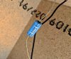
What I found were two piddly little caps: one in line with the mid; one in line with the tweeter. They seem be identical (maybe the mid has a "natural" roll-off?).

However -- in the very short time I've been doing this, i haven't seem caps marked like this. There doesn''t seem to be any MF symbol.

Rather, I'm seeing this printed on the sleeve:
NP (guessing this means non-polarized?)
85 ° C (guesing temp limit of some kind?)
9040
M07

I'm attaching a photo, too.
Can anyone guide me in finding the MF value, so I can get some replacements?

thank you in advance, for whatever wisdom you have to share :)
yamaha-cap.jpg
 
I’ve seen a cap like that before. And the value was on the other side. The temp and NP are obvious, and I think the 9040 is a date code. Not sure about the M07.

None of your caps have the value on the opposite side from the markings you’ve shown? The mid and tweeter probably have different value caps.

Also what’s the model of the speaker?
 
oh my dear god, I'm an idiot. I hadn't removed them yet, and the space is cramped... and it never occurred to me to rotate the caps around. Good lord.

Thank you @elitopus ! For helping a fool like me out :)

If anyone is actually curious... the value on the other side (I'm still face palming over here) is:
4.7 mfd , 50 v , +-10%

Speaker model is Yamaha NS-A-635.
 
Last edited:
Back
Top Bottom