**Edit 7/17/21: Skip to Post #51**
**Edit 12/27/20: Now seeing +800mV on Ch.2 output via DBT; Ch.1 is OK**
All original transistors and diodes, new electrolytic capacitors.
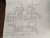
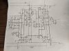
I'm seeing some negative DC offset on one channel, and my outputs from the op amp do not match the schematic. Various other voltage test points don't match the references in the schematic either.
-1.7VDC at Channel 2 output [varies, usually around -2V, but has gone up to -4V at times, seemingly randomly] EDIT: Now, on powerup, it initially is - 300mV but falls to around -900mV where it stabilizes.
0.0VDC at Channel 1 output
45V power supply good; IC supply 10V also good (see below)
Measurements of IC1 (739 dual op amp) - all V(DC)
Pin 1: -0.3 [Ch.1 WRONG - should be 1.75]
Pin 2: 9.2
Pin 3: 6.2
Pin 4: 6.2
Pin 5: 0.0
Pin 6: 0.0
Pin 7: -9.9 [GOOD - power supply]
Pin 8: -0.1
Pin 9: 0.0
Pin 10: 6.2
Pin 11: 6.3
Pin 12: 8.9
Pin 13: -0.3 [Ch.2 WRONG - should be 1.75] EDIT: Now +30mV
Pin 14: 9.9 [GOOD - power supply]
I've removed and tested the following transistors in my cheap transistor tester, results OK:
Q200, Q201, Q204, Q205, Q206, Q212
I've tested the following diodes as OK:
D207 (out of circuit), D208 (in circuit)
I've tested the following resistors as OK in circuit:
R216, R224, R237
Service Manual available here:
https://www.crownaudio.com/en/site_elements/d-150a-service-manual-part-1
https://www.crownaudio.com/en/site_elements/d-150a-service-manual-part-2
Would really love any suggestions as to where to go next. Do we think the op amp is bad? I tested a second one from another D150A I have on deck for repair, no change. Thanks.
**Edit 12/27/20: Now seeing +800mV on Ch.2 output via DBT; Ch.1 is OK**
All original transistors and diodes, new electrolytic capacitors.
I'm seeing some negative DC offset on one channel, and my outputs from the op amp do not match the schematic. Various other voltage test points don't match the references in the schematic either.
-1.7VDC at Channel 2 output [varies, usually around -2V, but has gone up to -4V at times, seemingly randomly] EDIT: Now, on powerup, it initially is - 300mV but falls to around -900mV where it stabilizes.
0.0VDC at Channel 1 output
45V power supply good; IC supply 10V also good (see below)
Measurements of IC1 (739 dual op amp) - all V(DC)
Pin 1: -0.3 [Ch.1 WRONG - should be 1.75]
Pin 2: 9.2
Pin 3: 6.2
Pin 4: 6.2
Pin 5: 0.0
Pin 6: 0.0
Pin 7: -9.9 [GOOD - power supply]
Pin 8: -0.1
Pin 9: 0.0
Pin 10: 6.2
Pin 11: 6.3
Pin 12: 8.9
Pin 13: -0.3 [Ch.2 WRONG - should be 1.75] EDIT: Now +30mV
Pin 14: 9.9 [GOOD - power supply]
I've removed and tested the following transistors in my cheap transistor tester, results OK:
Q200, Q201, Q204, Q205, Q206, Q212
I've tested the following diodes as OK:
D207 (out of circuit), D208 (in circuit)
I've tested the following resistors as OK in circuit:
R216, R224, R237
Service Manual available here:
https://www.crownaudio.com/en/site_elements/d-150a-service-manual-part-1
https://www.crownaudio.com/en/site_elements/d-150a-service-manual-part-2
Would really love any suggestions as to where to go next. Do we think the op amp is bad? I tested a second one from another D150A I have on deck for repair, no change. Thanks.
Last edited: