• The move to the new server is done. There are some software and database maintenance updates in process. This has us passing the hat around to help out. We appreciate any donations. Seriously, even a dollar helps. The payment page may be found here - https://www.audiokarma.org/support.html

Crown D150A - Puzzled. Fixed itself, then distortion came back. DC offset.

It's back together. New trimmers, new 1N4004s, some new transistors here and there.

Now seeing the +power supply voltage on BOTH channels! (Around +30V on the DBT; bulb is dim, though.)

The service manual suggests that + DC offset on both channels could come from two things, but unfortunately neither appear to be the case for me.

Potential cause #1: Shorted D4 (the +10V op amp power supply zener) ... but mine is good
Potential cause #2: Bad op amp ... but I continue to see the voltage on both channels with the op amp removed

So, it's something else. I'm in the middle of compiling voltage measurements for clues, no eureka moments yet. Scratching my head as to how the positive rail voltage is getting into both signal paths ...

All pre-drivers and drivers and outputs are good (or, were tested to be good earlier at least).
 
Last edited:
A step in the right direction - Q102 / Q202 are associated with the wrong parts in the service manual.

The service manual lists Q102 and Q202 as 2N3859. So I re-installed those.

I vaguely remembered pulling out some odd parts that I didn't see listed in the manual - one A92, one A93.

Re-installing the A92 / A93 at Q102 / Q202, my DC offset is much better. Channel 1 is perfect now, but Channel 2 I am seeing 800mV. Time to diagnose that ... kinda back to where I started, lol.

Just a public FYI that the D150A does not use 2N3859 at Q102/Q202, as stated by the service manual! It uses MPSA92 or MPSA93! Which makes sense given the voltages!
 
Last edited:
Still seeing ~800mV at Channel 2 output. IOC light on.

The 800mV is present in the feedback signal path. Here are some of the differences compared to the good channel ... maybe someone who understands this circuit better than I can use this to narrow down the possibilities?

Q211 / Q111:
Q211: Base has 800mV, C has 2.45V, E has 150mV. Q211 is the original 2N3859 device which tested OK out of circuit.

The good channel, Q111, has 0V at its Base, and reference voltages on C (1.45V) and E (-.65V).

Q204 / Q104:
Q204: Base has 580mV, E has ~750mV, and C is unstable between +50mV to -20mV! D208 is a Germanium diode that tests OK; C210 is a 200pF cap that tests good out of circuit. Q204 is the original 2N4125 that tested OK out of circuit.

On the good channel, Q104 Base has -148mV, E has -0.5mV, and C has -0.66V (which matches reference).

I'm also seeing 33mV on pin 8 of the opamp, Channel 2's inverting input. It should be close to 0.0mV; the good channel's inverting input is -0.3mV.

Lots of data points, but not seeing a pattern just yet.
 
Went down the service manual's suggestions ... I'll list what I checked.

I first checked the " Small DC Offsets" suggestions ...

1. No broken ground on input level control (R105, R205)
2. Input jack hot lead is shorted to ground, so input controls are functional
3. D200 is good (replaced with new 1N4148 just to be sure)

Then I checked the "Positive Offset - Single Channel" suggestions ...

1. IC op amp - good (I swapped back and forth with a spare good one)
2. Q200 not leaky or shorted (swapped with Q100)
3. Q201 not open (swapped with Q101)
4. Q206 not open, leaky, or shorted (swapped with Q106)
5. Q205 not open, leaky, or shorted (swapped with Q105)
6. Positive pre-driver Q207 not leaky or shorted (swapped with Q107) ... have not yet checked driver (Q209) or output device (Q210) but both tested OK out of circuit
7. Q211 not shorted (swapped with Q111)

Sooo ... Other than swapping drivers and outputs channel to channel, that's it for the manual's suggestions.
 
Swapped drivers and outputs between channels, to round out the service manual suggestions.

NO change.

So ... I guess it's not a transistor.
 
Absolutely - thanks! Crown still has them on its website:

https://www.crownaudio.com/en-US/site_elements/d-150a-service-manual-part-1
https://www.crownaudio.com/en-US/site_elements/d-150a-service-manual-part-2

Part 2 has the schematic, p.21 of the PDF. Note that R108 and R208 are absent in my unit, and R128/228 is around 180ohms (actually R128 measures 150ohms, R228 measures 180ohms).

I've continued to swap parts around and take measurements today. I haven't found a bad part yet, but the Channel 2 measurements are all messed up.400

For example, D207 cathode has ~500mV on it; Q204C is -400mV but B is +400mV and E is +570mV.

Note that it's hooked up to a DBT so the specific voltages are fluctuating a bit, but the positive offset in Channel 2 signal path remains.

Thanks in advance for any help!
 
I'd stop swapping parts, check the good channel is still working, and then focus on the wrong voltages you are finding.

I can check the schematic tomorrow and see if that makes some sense, perhaps I can see something obvious that you didn't see yet.

I think you need to check stage by stage, starting at the input to the 1st amplifier stage. If something is not ok there, that voltage will be amplified. Let's focus on the input by now.
 
Thanks, I sure hope so!

I checked all diode and B-E bias and found some interesting things but no smoking guns though. One is reverse biased on the bad channel, but the equivalent part is forward biased on the good channel. It's D206 that is reverse biased on the bad channel, but forward biased on the good channel. There should be slight negative voltage at the cathode, but D206 has positive 30mV at the cathode which may be related to the +400mV at Q204's base. This is supposed to be negative - and the emitter is in the feedback circuit (maybe this is the problem)? But Q204 has been verified to be good multiple times over.

I also noticed that Q213's bias is way off ... I've only got -27V at Q213B compared to -33V at Q113B - it's through the DBT, so the negative rail is -34Vish. The base of Q213 is supposed to be ~1V biased above the negative rail, not 6.6V! I think this basically means I've got around 6 times too much current coming from Q212's collector. Q212 is an original 7304 PNP that's been previously swapped over and back with the good channel and not made any difference.
 
You need a method and check step by step and go forward step by step. A bag full of information is useful but only when you organize that information and trace a plan.

If you can, write on the schematic the voltages in 2 colors, good channel (or expected voltage) and bad channel in a different color. Think we don't have the unit here and we need some easy way to follow the circuit and your measurements.
 
Sounds great - I have the basics already, but I have been writing them out here and comparing to the values of the good channels without displaying them on the circuit diagram. I'll make a more helpful guide ASAP.

On methodology - I started with the DC voltage at the output ... on the DBT it is between 600mV and 800mV depending on when I look at it. Compare that to the good channel which should be 0V.

I traced the voltage backwards, on the positive side back to Q207 base / D202 anode which should be around +1.5V. I measure +2.1V. The voltage I measure is exactly the DC offset higher than the reference value (600mV = 2.1V - 1.5V).

I noticed that the base of both Q203 and Q204 is biased with positive voltage, whereas on the good channel Q204 is biased with negative voltage.

Anyway, this is the best methodology I can think of, but I'd also love advice as to how to formulate a method to diagnose this circuit, and how to go step by step so we can use the info in a way that's helpful.

I'll work on writing more of the reference values and actual measurements in a better way so it's easier to follow. Thanks a ton for the help.
 
I see you reported a Dc offsetin both channels, almost the same, and then one channel was fixed and now you have just one bad channel.

What's the reaction of the circuit and the DC offset if you adjust it following the service manual?
 
I see you reported a Dc offsetin both channels, almost the same, and then one channel was fixed and now you have just one bad channel.

What's the reaction of the circuit and the DC offset if you adjust it following the service manual?

Yes, the DC offset in both channels was from installing the wrong devices as Q102 / Q202. That was a minor detour :p from the initial issue which remains: the DC offset in Channel 2.
Adjusting R200, output offset, does adjust the DC offset up and down by around +/- 100mV either way ... but doesn't solve it.

I think this may be because of the ~30mV I am seeing at the op amp's inverting input for Channel 2 (pin 8) ... compare to 0mV at Channel 1's inverting input (pin 6). I just can't tell if the 30mV inverting input is a symptom of the problem, or the source of the problem.
 
Last edited:
What's happening around Q200? If R208 is not present, the voltage at pin 13 should be set by the R206 - R207- Q200- Q201 -R216 network. I'd guess something around there is not conducting as it should, a resistor out of specs, a transistor backwards, an open circuit due to a bad soldering, some oxidized connection, whatever.

Can you post a pict of your notes on your schematic, showing the input IC, or the whole channel in question?

What happens when you adjust input offset?

BTW, if the unit is not shorted, you should apply the full voltage, not with the DBT.
 
Last edited:
Seems pretty much the same at Q200 (bad ch.2 / Q100 values on good ch.1)
Base: 9.1V / 9.1V
Collector: -4.8V / -5.0V (note that this deviates from the manual, and from the originally measured values, substantially ... nonetheless, there's no DC offset on Ch.1 with this value present)
Emitter: 9.8V / 9.8V

I'll go measure the Op Amp pins and mess with the input offset.

Still working on a better picture showing measured values against the other channel's equivalent values as well.
 
OK. If you can just print a clean schematic and write voltages. Comparing channels should show where the problem is. Following voltages written on a text is quite difficult, but on a schematic they are easier to follow.
 
Will do so! I will print it now.

I did just verify that the input offset pot does not alter the DC offset.

The Op Amp pins measure (again this is through a DBT, no input, gain all the way down on both channels):

1: -4.2V
2: 9.0V
3: 6.2V
4: 6.2V
5: 6.0mV
6: 5.4mV
7: -9.8V
8: 46.5mV
9: 6.5mV
10: 6.3V
11: 6.2V
12: 9.1V
13: -4.0V
14: 9.8V
 
I figured out how to get the circuit diagram into powerpoint, so I can just label the values and color code them.

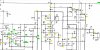
I wish I could upload a full resolution picture of the whole thing, but can't figure that out. So I've taken screen shots, pasted them into MS Paint, saved as JPEG images and uploaded.

Here's good channel 1 ...

D150A Ch.1 Diagnosis 20201228.jpg

Here's bad channel 2 ...

D150A Ch.2 Diagnosis 20201228.jpg
 
Back
Top Bottom