• The move to the new server is done. There are some software and database maintenance updates in process. This has us passing the hat around to help out. We appreciate any donations. Seriously, even a dollar helps. The payment page may be found here - https://www.audiokarma.org/support.html

Denon POA 6600 Thread

Hi James,

I now saw your POA-6600 thread.
I'm curious to know how the OPA1642 performed in your monoblock amp. I have a Denon PMA-737 integrated which uses the M5218 as DC Servo, too. After putting in an IC socket and trying a bunch of different opamps, I found that the "old" FET input TL072 vastly outperforms the stock one and is even better than the 5532. But this was in the PMA-737.
An opamp acting as DC Servo is almost always in the audio path, so I wanted to try a few ones, including newer ultra-low noise ones.
I just wanted to share this here: a while ago, last year, I was advised to increase the supply capacitance from 47uF to 100uF for the opamps to guarantee that their Icc (supply current) wouldn't drop with the voltages too much using another opamps with a higher Icc like the 5532 (8mA to 16mA!!!), but that did not happen. I left the 100uF caps in any way because they are new caps. Supply voltage dropped from 14.9V to 3V using OPA2134 and the L1113 and DC offset raised to over 250mV with them. OPA2107 was okay with current and voltage but the sound was pretty much the same as the M5218P.
The 5532 (BJT) sounded dull and lifeless, worse than the stock M5218. But the TL072 surprisingly sounded much more vivid with no voltage/current drop. The other good thing about the TL072 was that the DC offset dropped from ~5mV (stock M5218) to around 1.4mV.

Below is a quick list of the opamps used in place of the Mitsubishi M5218P, which is not (nowadays) considered a good opamp for audio.
A quick reference of parameters:

Opamp - noise in μV or nV - bandwidth in MHz - slew rate in V/μs - Supply current (Icc) in mA - topology BTJ or Fet

M5218P
- 2μV - 7MHz - 3V/μs - Icc 3mA ~ 6mA (p/ch) / BJT

TL072 - 15nV / 4MHz / 16V/μs / Icc 1.5 ~ 2.5mA (p/ch) / Fet
OPA2107 - 8nV / 4.5MHz / 18V/µs / Icc 4.5 ~ 5mA (p/ch) / Fet
LT1113 - 4.5nV / 5.6MHz / 3.9V/μs / Icc 5.3 ~ 6.5mA (p/ch) / Fet
JRC4558 - 8nV / 3MHz / 1.7 V/μs / Icc 3.5 ~ 5.7mA (p/ch) / BJT - 178mV

OPA2134 - 8nV / 8MHz / 20V/μs / Icc 4mA ~ 5mA (p/ch) / Fet
NJM2068 - 0.56µV / 27MHz / 6 V/μs / Icc 5mA ~ 8mA (p/ch) / BJT
NE5532 - 5nV / 10 MHz / 9V/μs / Icc 8mA ~ 16mA (p/ch) / BJT

* Still to try out (sometime in the future) ==================
* OPA1678 - 4.5nV / 16MHz / 9V/μs / Icc 2mA ~ 2.5mA (p/ch) / CMOS
* OPA1642 - 5.1nV / 11MHz / 20V/μs / Icc 1.8 ~ 2.3mA (p/ch) / Fet
* OPA2189 - 5.2nV / 14MHz / 20V/μs / Icc 1.3 ~ 1.7mA (p/ch) / CMOS
* OPA2210 - 2.2nV / 18MHz / 6.4V/μs / Icc 2.2 ~ 2.5mA (p/ch) / BJT
* OPA1662 - 3.3nV / 22MHz / 17V/μs / Icc 1.5 ~ 1.8mA (p/ch) / BJT
* OPA1602 - 2.5nV / 35MHz / 20V/μs / Icc 2.6 ~ 3.2mA (p/ch) / BJT
* OPA1688 - 8nV / 10MHz / 8V/μs / Icc 1.6 ~ 1.8mA (p/ch) / CMOS

OK. I don't have any OPA1642. But I did find some OPA1656 in my parts box. Also a Fet input op-amp.

So far I have only gotten one amp working and at the moment it has the stock NJM082BD and M5218P in it.

I was talking with my electronics friend about the choice of that 082BD in the IC501 position. His take is that an op-amp with a FET input can work in a circuit with a high overall input impedance and will work well with very little current flow. So he recommended sticking with that type of op-amp in that position.

I also have some TL082CP parts, which look to my uneducated eye like a bit faster and more robust version of the NJM082BD.

For the M5218 position I have several things that I can try, NE5532, NJM2068DD, OPA2134, LME49720 and a few more.

But first I have to get 2 amps working. :biggrin: As they say, "I'm working on that"

Anyway, please stick around. You always have good insights and thoughts.

:beerchug:,
James
 
Supply voltage dropped from 14.9V to 3V using OPA2134 and the L1113 and DC offset raised to over 250mV with them. OPA2107 was okay with current and voltage but the sound was pretty much the same as the M5218P.
The 5532 (BJT) sounded dull and lifeless, worse than the stock M5218. But the TL072 surprisingly sounded much more vivid with no voltage/current drop. The other good thing about the TL072 was that the DC offset dropped from ~5mV (stock M5218) to around 1.4mV.
When I was first testing the first amp and before I got it working I also noticed that installing anything other than the stock op-amps dropped the supply voltage. I'm pretty sure that the amp was oscillating and changing the op-amps just made it worse.

Also almost all of the zener diodes were working at 0.2v to 0.4v lower than spec, so the supply rails were low to begin with. Replacing the zeners and the transistors in the voltage amp section seems to have made a big difference and I could at least put a TL082 in the amp without the supply voltages dropping. I haven't gotten any farther than that yet.

If your supply voltages are only 14.9v, and if they are supposed to be 15.1v like my amp you might want to check those HZ-15-2 zener diodes.

:beerchug:,
James
 
Yes.
My main goal with the PMA-737 was/is to see if a more precise (and suitable) opamp as DC servo could reduce even further the DC offset.
The "rough" M5218P keeps it around 5mV, not bad. But I thought a newer modern opamp, being in the signal path, with lower noise, Fet/Cmos input, and low Icc consumption could do it better.
The selection was made around the bandwidth and slew rate (not too far from the original) but with lower noise and lower Icc opamps to avoid instabilities.
I want to try out the other more modern ones at the bottom of the list, but they come in SMD parts, so I have to adapt them to PDIP package first.
Nice work with these beautiful POAs... :beerchug:
 
When I was first testing the first amp and before I got it working I also noticed that installing anything other than the stock op-amps dropped the supply voltage. I'm pretty sure that the amp was oscillating and changing the op-amps just made it worse.

Also almost all of the zener diodes were working at 0.2v to 0.4v lower than spec, so the supply rails were low to begin with. Replacing the zeners and the transistors in the voltage amp section seems to have made a big difference and I could at least put a TL082 in the amp without the supply voltages dropping. I haven't gotten any farther than that yet.

If your supply voltages are only 14.9v, and if they are supposed to be 15.1v like my amp you might want to check those HZ-15-2 zener diodes.

:beerchug:,
James
Yes. Other than the Zeners, the 47uF supply caps in the 737 needed to be increased to 100uF to provide an adequate power reserve for the other Opamps.
Okay, now I'll follow your thread. :thumbsup:
 
Yes.
My main goal with the PMA-737 was/is to see if a more precise (and suitable) opamp as DC servo could reduce even further the DC offset.
The "rough" M5218P keeps it around 5mV, not bad. But I thought a newer modern opamp, being in the signal path, with lower noise, Fet/Cmos input, and low Icc consumption could do it better.
The selection was made around the bandwidth and slew rate (not too far from the original) but with lower noise and lower Icc opamps to avoid instabilities.
I want to try out the other more modern ones at the bottom of the list, but they come in SMD parts, so I have to adapt them to PDIP package first.
Nice work with these beautiful POAs... :beerchug:
Thanks for the kind thoughts.

Here is exactly part of my problem, I simply do not have the experience to actually trace the signal path through the complete amp. It is too complex for my little brain and I get a headache trying.

The OPA1656 are also SMD parts, I had to mount them to adapter PDIP boards. With a fine tip and some liquid flux it went fairly easy. I think that it's something that we are just going to have to get used to doing if we want to use the newer op-amps.

I'm leaving on a 2 week vacation a week from tomorrow. When I get back I'll be making a large Mouser order and will include some of those OPA1642's.

:beerchug:,
James
 
I just looked, I still have a couple of OPA2107AP.
Also OPA2132P, OPA2134PA, OPA1602AIDR and OPA1612AID and of course LME49720 and LME49860MAX/NOPB.

James
 
I'm leaving on a 2 week vacation a week from tomorrow. When I get back I'll be making a large Mouser order and will include some of those OPA1642's.

:beerchug:,
James
Nice! Enjoy the vacation. :beerchug:

You may want to include a few other low-noise modern ones, for future projects.
The OPA2189 works at max. ±40V (±36V safe area) if you need a GOOD opamp for that high voltage.
The OPA1678 is designed for headphones and also operates at ±40V (±36V safe area).
The OPA2210 is just a 2.2nV low-noise device, a favorite in the DIY world for use in DACs without instabilities...
Just for the bookmark. :beerchug:

(±36V) * OPA1678 - 4.5nV / 16MHz / 9V/μs / Icc 2mA ~ 2.5mA (p/ch) / CMOS
(±36V) * OPA2189 - 5.2nV / 14MHz / 20V/μs / Icc 1.3 ~ 1.7mA (p/ch) / CMOS
* OPA2210 - 2.2nV / 18MHz / 6.4V/μs / Icc 2.2 ~ 2.5mA (p/ch) / BJT
 
It's an elegant design. I'm more repairman minded then design & analysis. It's been 30 years since I went to op amp school. But I do remember their feedback loops are crucial for gain & stability.
Fellow mechanic point of view...Don't connect your battery backwards, lol. Bad things happen. Polarized caps are like batteries.Those 3 polarized caps we're talking about are designed to be a one way street for DC. They block DC and pass AC. Notice the anodes of those 3 are tied to the positive source, +15v & +1.8. The cathodes are tied to the negative source. -15v & -1.8. I think the NP Wima's are cancelling the feedback loops to the op amp.
Here is a different question for you.
I'm sitting here looking at the schematic for the thousandth time.
It looks like C218, 219 (220µF) are doing local filtering/resivour for the +/-15v supply lines for the op-amps. Yes/no? That should help keep them stable, no?

So I go over and look at C524 & 525 and ask, what are they doing?
I mean, yeah, I see that C525 is directly between the +/-15v lines, and between the op-amps. and C524 is between the +/-1.8v supply that looks like it is going to the base(s) of the pre-drivers.
So they are doing local stabilizing? But why such a small value elco? Is that a case of the book keeping dept saying "That is enough and not one cent more", or the engineering dept saying "This is the exact value needed, not more or less"? Or what?

So, I'm kinda asking, what happens if some dumbass were to put say, a couple of 10µF/50v FR elcos there?

Is the law of unforeseen and unintended consequences going to come down and cut the head off of my snake?

:beerchug:,
James
 
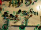
The protection section is worked. No surprises and no problems here. The diodes and resistors were replaced as in the other sections, 1N4148, SFR25 and RN60. The transistors were tested and re-installed.

DSC02632.JPG

Cheers,
James
 
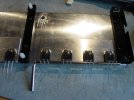
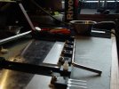
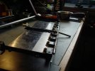
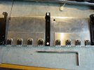
I gave it 24 hours of thought and decided to go ahead with the MJE15033G/32G drivers.
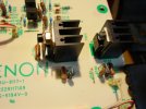
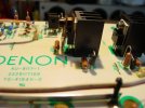
The nearly useless cross tip screws have been replaced with Allen head, using a cut down key they are now easy to tighten/loosen. The D509 MV-1YH thermal tracking diode has again been replaced with a 1N4148 and thermal paste with a piece of phenolic strip to press it against the transistor.

DSC02634.JPGDSC02636.JPG

The drivers were originally placed dry against the heat sinks. Now they have a thin layer of thermal paste.

:beerchug:,
James
 
I got paranoid now and went back and returned C547 and 591 to 10µF/50v elcos, I ran out of FR so used Panasonic FC. The Wimas are out of there and are now only installed in 3 positions that originally had BP elcos.

DSC02639.JPG


:beerchug:,
James
 
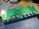
I'm thinking real strongly about doing this.
DSC02641.JPGDSC02640.JPG

I will decide in the morning. If I do it there will be a test in the afternoon.
My mentor stopped by for a beer this afternoon and we discussed it. He is of the opinion that there will be no danger.

Then I will go back into the other amp and retrofit it before doing a 2 amp test.

:beerchug:,
James
 
Random thoughts:

A view of the depths of my ignorance: My Sensei was here this afternoon and I showed him where the burnt resistor was and expressed my puzzlement that the 1k resistor burned before the 47 ohm part. Answer: "Of course. There is much more voltage drop across the 1k part and it is under a greater load and will burn first". So I was thinking exactly backwards. Not the first time.

I rechecked the 3 shorted transistors. The driver had 29 ohms resistance between base/collector and base/emitter and 0ohms between collector/emitter. The outputs had about 0.7ohms between base/collector and base/emitter and 0ohms between collector/emitter.

After I made those last few posts I was sitting here reading the news on my PC and listening to Wife talk. For some reason I reached up and touched my right ear. It was cold. I touched my left ear. It was very warm.
I stepped over to Wife and asked her to touch my ears. She said that my right ear was cold and my left ear was very warm.

After that I had a light supper and then went in the living room and listened to Led Zeppelin 1, 2 and 3. I noticed that both of my ears were cool.

Random fact: When we are in our hobby room sitting at our PC's Wife sits about 2 meters to my left. Coincidence?

:beerchug:,
James
 
Here is a different question for you.
I'm sitting here looking at the schematic for the thousandth time.
It looks like C218, 219 (220µF) are doing local filtering/resivour for the +/-15v supply lines for the op-amps. Yes/no? That should help keep them stable, no?

So I go over and look at C524 & 525 and ask, what are they doing?
I mean, yeah, I see that C525 is directly between the +/-15v lines, and between the op-amps. and C524 is between the +/-1.8v supply that looks like it is going to the base(s) of the pre-drivers.
So they are doing local stabilizing? But why such a small value elco? Is that a case of the book keeping dept saying "That is enough and not one cent more", or the engineering dept saying "This is the exact value needed, not more or less"? Or what?

So, I'm kinda asking, what happens if some dumbass were to put say, a couple of 10µF/50v FR elcos there?

Is the law of unforeseen and unintended consequences going to come down and cut the head off of my snake?

:beerchug:,
James
Yo. I think all caps in question are supply filters.
 
Back
Top Bottom