• The move to the new server is done. There are some software and database maintenance updates in process. This has us passing the hat around to help out. We appreciate any donations. Seriously, even a dollar helps. The payment page may be found here - https://www.audiokarma.org/support.html

Denon POA 6600 Thread

Would those work for ya? I found 2 more if you're interested. Thought that one was best bang for buck
Hah! I didn't even look at DigiKey.

Yes, those look very good.

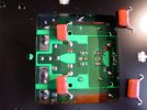
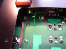
One thing that I forgot to do earlier was to add some 0.01µF film caps to the filter caps and I am doing that right now.
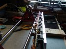
DSC02489.JPGDSC02491.JPG
So I took some rough measurements. 4 pin caps with 2 dummy pins.
Looks like about 22mm between +/- and 20mm between the dummies.

Snip off the dummy pins and it would probably be a drop-in fit.

I wonder if CDE is participating in The Great Capacitor Swindle? This is the problem that I see with new 10000µF caps.
Lets say that the original caps are now down to 9000µF. New "10000µF" caps will only be 9000µF now. So the only potential gain by recapping these would be a possibly lower ESR if the old caps have risen in ESR.

Cheers,
James
 
Last edited:
I wonder if CDE is participating in The Great Capacitor Swindle? This is the problem that I see with new 10000µF caps.
Lets say that the original caps are now down to 9000µF. New "10000µF caps will only be 9000µF now. So the only potential gain by recapping these would be a possibly lower ESR if the old caps have risen in ESR.
Have ya ever reformed an older cap per chance? The big filter caps like that I mean.
 
So we really don't know what fixed the problem, but I'm glad the amp is working.
Agree, but we can make a reasonable guess that one of those transistors wasn't playing nice with it's friends.

While waiting for my friend to have the time I considered re-installing all 10 original parts and then replacing them with a new one one at a time.
But that would have taken up to 10 times longer than just replacing them all and involved removing the board each time, raising the risk of unintended damage.
It wasn't elegant, and it wasn't proper troubleshooting, but it seems to have worked worked.

Cheers,
James
 
When the problem first popped up back in September I sat down with my tech friends and the schematic and we worked on a plan, with the suspect items being in the idle current section. D509, D527, TR551 and C524 being on the top of the list.

When every part in the entire idle current section tested good we shifted to looking into the output section, in retrospect a mistake. After that I started checking parts a bit at a time until I had actually tested every single part on the entire board with the exception of the zener diodes, the 2 opamps, and the 3 caps that I mentioned in post #49.

There some things that I will not do. I won't re-install a carbon film resistor when I have a huge selection of 1% metal film resistors. I won't re-install an old diode. I won't re-install an old electrolytic cap. This meant that eventually a large portion of the board had been replaced with new parts and every solder connection had been renewed.

Texting with my friend morfeora the autocorrect on my cell phone kept changing Denon to Demon, and eventually by the end of November I was starting to agree with it.
At that point I decided to make a backup plan so that I could at least finish up the organization of the new stand and get the 2-channel amp out of the way.

So I bought 4, eventually 6 Marantz MA500 monoblocks and spent December and January restomodding them.
https://audiokarma.org/forums/index.php?threads/marantz-ma500-thread.1047034/

That brings us up to about the point where the early part of this thread started.

Cheers,
James
 
The front panel has been re-worked from this:
DSC01813.JPG

And is seems that I failed to get a better finished photo than this one:
DSC01849.JPG
Cheers,
James
 
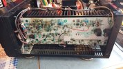
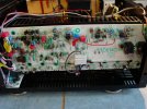
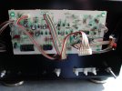
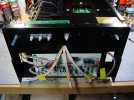
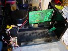
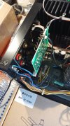
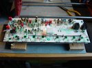
Getting at the power supply board is not all that easy, you have to basically disassemble the amp. But other than the main filter caps it has been recapped and re-soldered.

DSC01817.JPG

Cheers,
James
 
Early on I started thinking about buying a 3rd amp to eventually refurb and keep as a backup in case I had a problem with a main amp.
One popped up on ebay, listed as damaged, for half the price that I paid for the first 2, so I bought it.

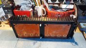
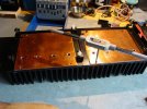
It does have problems, but when I opened it I found the most interesting thing. The heat sink has 2 large 2mm thick solid copper heat spreaders attached to it. This was rather intriguing, and after looking I realized that my heat sinks were at least partially drilled and tapped to accept the spreaders.
And they are shown in the service manual, but only for the E2 models, Reference #62 "Radiator".

IMG_20231011_170913_325a.jpg

A few weeks later I saw that someone in France was parting out a unit and had the heat sink with heat spreader and an input board listed. I bought them both.

James
 
The odd thing is that between the 4 heat sinks that I now had they were all slightly different.
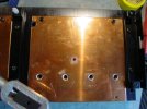
Some had mounting holes for the radiators only drilled and tapped in the upper 2 corners. Some in all 4 corners. And while the plate has a hole in the middle none of the heat sinks had a hole there.

So I drilled and tapped 2 heat sinks for all 5 mounting screws.

DSC01845.JPGDSC01846.JPGDSC01848.JPG

Cheers,
James
 
So, all of the output transistors are mounted behind the main board. I can only guess that people remove the heat sink, mount the transistors to it. mount the board, and solder them in place. Trying to get the transistors positioned otherwise would be a nightmare.

The thing is, the heat sink has such a deep overhang that there is very little room to try to get an iron in there and solder the leads. I would think that doing it this way kinda sucks.

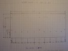
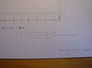
I measured the heat sink and all of the hole positions and made a sketch. These photos aren't great, I'll try to remember to get the scanner out and make a good scan of the sketch.

DSC02517.JPGDSC02518.JPGDSC02519.JPG

Then I bought a piece of aluminum, 5mm thick, 310 x 100mm.

James
 
5mm is in reality a bit thick. It would probably would have been better to buy 3mm or 4mm. The piece was slightly curved from being sheared from a larger sheet, and the ends were not perfectly square to the sides.

So it took a bit of careful bending and filing to get it flat with square ends.

Where the heck is this going?

Here:
DSC02218.JPGDSC02219.JPG

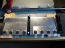
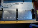
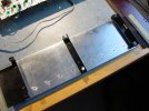
I made a output transistor mounting plate, 20mm shorter on the bottom, to make it easier to solder the outputs in place.

Cheers,
James
 
I also cut and drilled a pair of 2mm thick plates to simulate the copper heat spreaders, so this tool can be used with or without the spreaders and get the outputs perfectly positioned.

DSC02292.JPG

Cheers,
James
 
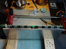
I took a 5mm steel rod, placed it up against the base of the transistor body and rolled the leads up and a bit past 90°. The roll hopefully will allow the leads to flex slightly with thermal expansion and reduce stress on the solder pads. I didn't like the square 90° bends in the leads on the original outputs.

Bending them a bit past 90° means that when the board is mounted in place on the frame it presses lightly up against the leads and they are held nicely in place for soldering.

DSC02295.JPGDSC02298.JPGDSC02300.JPGDSC02302.JPGDSC02306.JPG
This worked rather nicely and it was super easy to get the iron in there to solder the leads.

Cheers,
James
 
Back
Top Bottom