• The move to the new server is done. There are some software and database maintenance updates in process. This has us passing the hat around to help out. We appreciate any donations. Seriously, even a dollar helps. The payment page may be found here - https://www.audiokarma.org/support.html

Denon POA 6600 Thread

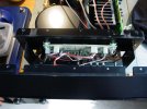
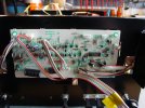
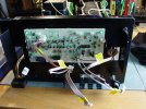
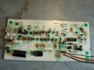
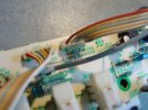
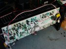
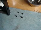
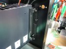
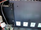
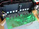
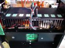
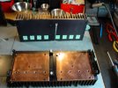
As mentioned earlier, to remove the front panel of the amp there are 3 screws on the top and 3 screws on the bottom, one of which is a flathead countersunk screw hidden inder the left foot as viewed from the front.
There are a bunch of plugs to label and disconnect.

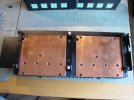
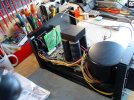
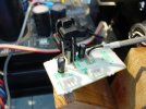
DSC02530.JPGDSC02531.JPGDSC02537.JPGDSC02541.JPG

Cheers,
James
 
There are 11 elcos on the board and 4 zener diodes. After seeing that all of the zeners on the amp board were not at spec I will pull these and test them.

DSC02542.JPGDSC02543.JPG

Cheers,
James
 
I started out with separates, a Yamaha C-50+M-50. Then went to an integrated for 20 years, an AX-1090. Then back to separates. And now even more separate.

I would not willingly go back to an integrated. Channel separation and sound quality is just better with a dedicated pre and power amp. Going to mono power amps has been a revelation. Trust me, it will give you a Chubby.

Receivers never interested me at all. Radio just takes me to that thread about being angry all the time.

:beerchug:,
James
I've got a couple of power amps/monoblocks on my "dream list", but I love integrateds and there are some on my "dream list" ahead of the power amps... The integrateds I like the most are real dual mono, two transformers with separate filter/rectification... still not as good as a true separate of course, but the "best of both worlds"
 
There are 11 elcos on the board and 4 zener diodes. After seeing that all of the zeners on the amp board were not at spec I will pull these and test them.


Cheers,
James
I realize that I have a different philosophy than most people when it comes to originality of parts/components, (originality be damned, if a replacement works as it should then I won't think twice, and ALL electrolytics get replaced, even if they measure well), but I was watching some videos and thinking about pulling parts to test... if something is coming out to test and I already have a suitable replacement on hand, I might as well just go ahead and replace it.

What do you think?
 
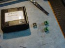
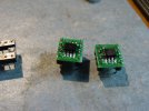
I had already gotten ready to mount the OPA1656 opamps to adapter board so befor getting started on that front board I went ahead and soldered them.
This is a case where a fine tip and liquid flux is mandatory.

DSC02545.JPGDSC02546.JPGDSC02547.JPG

Not the best soldering that I have ever done but not the worst either, I'm thinking that they should work.

Cheers,
James
 
I realize that I have a different philosophy than most people when it comes to originality of parts/components, (originality be damned, if a replacement works as it should then I won't think twice, and ALL electrolytics get replaced, even if they measure well), but I was watching some videos and thinking about pulling parts to test... if something is coming out to test and I already have a suitable replacement on hand, I might as well just go ahead and replace it.

What do you think?
This is my method exactly.

One, it is about doing maintenance. And if possible it's nice to only have to go in once.
Two, I want to limit how many times I solder something in a position on the board. So far I haven't destroyed any traces and don't want to start.
Three, concerning many types of parts once an old one is removed I am not going to re-install an old part if I have a new one on hand unless it is something like a transistor that I am sure is good and is hard to replace.
(that 3rd one already bit my ass on the first amp)

Fourth, I have gotten in the habit of replacing carbon film resistors with metal film, at an absolute minimum those in the signal path but generally every one in the entire section that is processing a signal.

Fifth, I like to test and document all the parts in an area where I am working. And I know that I am going to resolder every single part on every board.

So the bottom line is that if I only want to be soldering something once, when the part gets removed, tested, and if it is a carbon film resistor, electrolytic cap, plain ceramic disk, diode, zener diode or anything questionable it gets set aside and replaced with a new part.

I do not care in the slightest if other people do not like that. They get to do what they want with their property, I'll do what I want with mine.

Cheers,
James
 
Last edited:
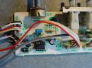
Didn't get a lot done today, re-soldered and re-capped the front board.

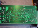
DSC02553.JPGDSC02550.JPG

Caps.
I continue to believe that these first 2 amps are low hour units. The caps in the first amp were nearly all near nominal and so far this one also. Nonetheless, as with the other one all elcos except for the main filter caps will be replaced.

Rant Mode ON: The Great Cap Swindle just pisses me off more and more. It is a crapshoot if what we buy is at the stated value or not. In this regard Panasonic FC, FM and FR seem to be better than some other brands and especially FM are near nominal more often than not. Rant Mode OFF.

C102: 1000µF/35v. I bought 2 different FC for this position, 35v and 50v. The 35v all tested between 965µF and 970µF. The 50v tested even lower at an average of 945µF. This value isn't available in FM or FR. I used the 35v part.
I'm wishing now that I had ordered some UCC KYB 1200µF/50v for that position. They probably would have tested at around 1080µF.
https://www.mouser.de/ProductDetail/Chemi-Con/EKYB500ELL122MK40S?qs=IYueExuAvkp/sidVSI1iLQ==

C103: 0.47µF/50v. Used a Wima 63v part.
C104: 100µF/35v. Panasonic FM 50v.
C105: 1µF/50v. Wima in 63v.
C107: 33µF/16v. Panasonic FM 35v.
C108: 220µF/63v. Panasonic FM 220µF/10v.
C110: 100µF/6.3v. Panasonic FM 10v.
C111: 10µF/16v. Wima 50v.
C112: 10µF/50v. Wima 50v.
C113: 47µF/35v. Panasonic FC 50v.
C120: 22µF/16v. Panasonic FC 35v.
For C113 and 120 I had FC, FM and FR, the FC tested nominal so I used them.

Zener diodes. I had no luck finding a nominal value replacement for D113 and D123. I broke my rule and re-installed them.
D105: HZ15-2, nominal value 14.8v. Used 1N965B. Bought 100 and it was easy to sort them and find a 14.8v part.
D110: HZ5C-1, nominal value 5V. Used a MTZJ5V1SB.
D113: HZ7B-3, nominal value 7.15v. Original part tested at 7.12v. Re-installed.
D123: HZ9B-2, nominal value 8.7v. Original part tested at 8.65v. Re-installed.

For the rest of the board I only re-soldered the parts and did not remove anything.

Then the board was cleaned and re-installed. After that I pulled the input switching board, that will get worked tomorrow.

Cheers,
James

edit: btw, R131 was re-positioned a bit after the photo was made so that it is not pressing up against that 10µF Wima. I don't know how hot it might get.

 
Last edited:
Just out of curiosity/learning, I tried finding replacements. Is there any reason the ones I found here wouldn't work for you?

D113: HZ7B-3, nominal value 7.15v. Original part tested at 7.12v. Re-installed.
NZX7V5A,133, 7.15V nominal
D123: HZ9B-2, nominal value 8.7v. Original part tested at 8.65v. Re-installed.
NZX9V1A,133, 8.7V nominal
 
Just out of curiosity/learning, I tried finding replacements. Is there any reason the ones I found here wouldn't work for you?


NZX7V5A,133, 7.15V nominal

NZX9V1A,133, 8.7V nominal

I'm sure that they would be perfect if I had thought to look at DigiKey. :biggrin:

I don't order from them very often because they ship with UPS, and UPS is a PITA here because they never deliver to me but rather drop my shipment at different pack stations all over town, which generally pisses me off.

:beerchug:,
James
 
I don't order from them very often because they ship with UPS, and UPS is a PITA here because they never deliver to me but rather drop my shipment at different pack stations all over town, which generally pisses me off.
That's odd cuz I only order from digi-key & they give me a dozen delivery carrier options. Mouser isn't friendly on my order device thingy.
 
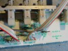
I got the input switching board worked today.

All of the resitors on this board are either passing signal or working around signal. All of them are carbon film and all of them tested very nominal. All of them were replaced with Vishay SFR25 400mW and 500mW metal film except for one, R405, where I used a CMF55 industrial 500mW, just because I had some. All were tested and sorted under 1% tolerance.

There are 2 elcos doing decoupling on the voltage supply lines for the balanced input op-amp, C403 & C404, 10µF/50v. They were replaced with Panasonic FR 47µF/50v plus a 0.1µF TDK MLCC C0G(NPO) in parallel. The only other cap on the board is a 100pF, C402. It looks like a PP, tested nominal and was re-installed.

The JRC2068DD op-amp was replaced with a socket and a LME49720.

The rest of the connections were re-soldered, the board cleaned, and re-installed in the amp. The switches and volume pot have no openings to get any Deoxit into. I decided not to open them.

DSC02564.JPGDSC02565.JPGDSC02566.JPG

There is one resistor that is not shown in the schematic, and the silkscreen ID for it is obscured by the marking for a large through hole. It sits right above the position for C405 (which is not populated on my amp. 100K ohms.

Tracing out the traces it sits between the ground plane and the junction of C404 and R405 and connects to a post on the balanced input switch. So I think that this is there to shunt a short on the input to ground.
In this photo the resistor is above R405 and the C405 position.
DSC02562.JPG

Cheers,
James
 
Last edited:
Preparing for the removal of the main amp board and heat sink before working the power supply.

There is an odd mix of machine screws and sheet metal screws holding some parts of the amp together and between the 3 amps and 4 heat sinks that I have they are not all the same. It is very easy to loose track of which screws were in which positions.
DSC02567.JPG
For instance: The amp board is held in place in this amp with 3 machine screws and one sheet metal screw, which is in the bottom left corner holding the ground wires in place.
So when removing the board (and other parts of the amp) I lay the screws out in their removal pattern and then return them to their positions after getting the board out of the way.
Just saying, because this can save me from trouble and confusion later.
DSC02568.JPGDSC02571.JPGDSC02572.JPG

Cheers,
James
 
Now I just have to de-solder the posts for the 4 wire wrapped wires and I can set the board aside for later and start working the power supply.

DSC02570.JPG

Cheers,
James
 
There are 4 brackets holding the heat sink in place.

2 L-form brackets hold the bottom in place. My 3rd amp arrived missing these 2 brackets so I will have to make a pair. I made some measurements and will deal with that later.
DSC02573.JPG

On the left (amp front) and right (amp rear) there are brackets that fasten to the front and rear of the amp. There are cutouts in the front and rear panels that allow the heat sink to be removed without having to remove the panels.
DSC02576.JPGDSC02577.JPG

Warning: with the heat sink removed there are only a few screws holding the front and rear panels to the central support frame. Care must be exercised when moving the amp at this point, it would be easy to bend the panels.

Cheers,
James
 
Last edited:
At this point since I will be swapping the heat sink with one that has the copper heat spreaders I immediately transferred the mounting brackets to the "new" heat sink.
DSC02579.JPGDSC02580.JPG
Here again we have sheet metal screws holding the brackets to the "old" heat sink and the new one had M3 machine screws, which did not come with the extra heat sink that I bought.

I guess that I don't have to say that it pays to beep an assortment of extra amp hardware on hand. Even a totally trashed amp can contribute useful items to save the day at some point in time.
DSC02581.JPG

Cheers,
James
 
Now I can move on the project for today, working on the power supply.
DSC02583.JPGDSC02584.JPG
Note for anyone removing the PSU board:
There are 5 screws holding the board and 3 of them have fiber washers under the head. It's easy to loose track of where the washers go.
The 2 front screws and the middle screw have the washers, the right rear screw was bare, and the leaf rear screw has a cable tie-down clasp thingy that holds the power cord in position.
:beerchug:,
James
 
Last edited:
Before getting to the PSU there was one small chore to take care of. There are 2 small 10µF/35v caps on the little input board on the back panel, C301, 302. Since I need to get that and the balanced plug out of the way before I can tip the PSU over I went ahead and replaced those caps with Panasonic FM 10µF/50v. Wima caps will not fit here.

DSC02586.JPG
Naturally the rest of the board was re-soldered.
Here is a case where it really pays to label the connecting wires before unplugging them. CN7 and CN8 have the exact same plug. It would be easy to get them mixed up.

Cheers,
James
 
DSC02589.JPG

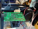
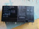
A while back I looked into relays. And found a nice one for the protection relay. In fact I had 4 of them on hand when I worked on the other amp.

And for some dumbass reason totally failed to replace that relay while I had the amp torn apart. The speaker relays are easy to get to and can probably be changed in a half hour. The protection relay can only be changed when the Power supply board is tipped to the side and that means taking out the heat sink and a lot of work. And I totally forgot to do that 10 minute job while I had the chance.

As my Dad was fond of saying, "That just burns my butt".

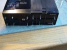
With this amp at least that relay was changed. Omron G4W-2212P-US-TV5-HP-DC24. 15A compared to the original 7A and it is a drop-in fit.
DSC02595.JPGDSC02596.JPG

Cheers,
James
 
Back
Top Bottom