• The move to the new server is done. There are some software and database maintenance updates in process. This has us passing the hat around to help out. We appreciate any donations. Seriously, even a dollar helps. The payment page may be found here - https://www.audiokarma.org/support.html

Desperate Cry for HELP with a Kenwood KA6004

selmafrog

Active Member
I recently purchased a Kenwood KA6004. The one I had in 1974 was stolen the night before I left the Army in Fort Riley, Kansas. I have purchased a Marantz, an NEC A10II, and a BOSE surround system, and none of those have come close to the sound I enjoyed from the Bose 501s, Dual 1229 Turntable, and the Kenwood KA6004.
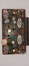
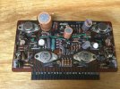
I have not powered it on. I did open it and it had a coat of dirt, dust, grime on almost everything. I cleaned some and then pulled the preAmp board - X07-1120-00.
Using an ERS meter on the capacitors returns what appear to be values close to expected,
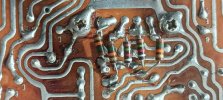
However, when I look at the backside of the board there are 5 resistors there which, to me, appear to be add-ons.
I have included pics.
Has anyone seen this type of add-on from the factory, or an update after production? If you have, what is the purpose of these? I am not an engineer, but the placement of a couple of these makes me wonder if these are bypassing the function of the diodes. Also, doesn't the placement of the ones in parallel with the original resistors lower the resistance to less than half of what the original resistor provided. Like: 18,000 X 15000\18000+15000 = something like 8100 ?
If this a manufacturer update, do you have an updated schematic to show the correct placement so i can try to verify?
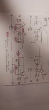
I have attached a copy of my crude drawing of, what I think is the affected part. The upper part is what I think is original, and the lower part is with the added resistors - the dotted lines, in pink are my attempt to show them as add-ons.
Thank you for any assistance.BackOfBoard.jpgCloseUp.jpgComparison.jpgFrontOfBoard_X07_1120_00.jpg
 
Register to hide this ad
I just spent the better part of two hours searching AK and the whole internet to try and find something to help you. Before I start rambling I didn't find a definitive answer for you, sorry. :confused:

first thing I wanna note: you are looking at your Main Amp board, not the preamp.

I searched all over and found a couple pictures of the rear of other boards from KA-6004 and I did not find any other examples with resistors like that.

Sorry I couldn't help, I really hope you get it figured out and get that beautiful amp working.

@Semanon did a restoration of a KA-6004 a couple years back, maybe he can provide some insight.
 
@analogwisdom thanks for the ping.

Mine matched the schematic from HiFi Engine. The added resistors look factory, so I’d assume that they are proper. Still, I’d check it against the schematic to see what’s up.

BTW, mine worked perfectly as shown.

Here are photos of the amp board.
E2895221-0402-434A-AD57-52BB1A706165.jpeg
3ABADDAA-7944-49DF-9FA1-745B412A0D62.jpeg
 
Last edited:
I’d build a DBT and fire it up. If the amp output isn’t shorted, check offset, the power supply voltages, then enjoy it. It is very sweet.

Are all the switches intact?
 
Last edited:
Ah… it’s all coming back to me like the hot fist at the end of a wet kiss…

When I got the amp, it had a lot of hiss and noise, like the wind blowing through the trees, variable in frequency and amplitude. The offset was high, something like 122 and 67 mv. I replaced all the caps: 30% were out of spec. I replaced the 2sc458 transistors with ksc1815 or ksc1845. I replaced the LTP transistors with ztx795 (ksc1845 would have done) which dropped the offset to under 5 mv.

Amp board and preamp were a piece of cake. The tone board was a bear, but doable, with patience. This is where most of the noise was coming from.

After the rebuild, it was a really sweet amp that I enjoyed for a couple of years.

I loved the rotary switch tone controls. Everything else is cheating.
 
Last edited:
This thread has changed my process for reconditioning audio equipment. I always take lots and lots of pics of the equipment as it comes apart. But when I was looking for pics AFTER the work, there were very few. I need to take WAY MORE after pics of the interior, not just exterior beauty shots.
 
Last edited:
This thread has changed my process for reconditioning audio equipment. I always take lots and lots of pics of the equipment as it comes apart. But when I was looking for pics AFTER the work, there were very few. I need to take WAY MORE after pics of the interior, or just exterior beauty shots.
Yes, I agree. I am in the middle of my first ever recap/resto on my beloved KA-7300 and when I was doing the Control board the other day I only took "before" pics... by the time I had got everything on the board redone and ready to put back together it was almost 9 hours in (newbie being very slow and methodical as to not screw anything up) and I was ready to be done with it, lol. I didn't take any after pics at all. I'm going to finish up the rest of the amp at some point soon so I'll be sure to take pics then.

I live in a very small house so I don't have space for an actual workbench, which means any time I want to work on something it's in the living room and needs to be completely assembled when I am done for the day. If I'm ever able to buy a house (just hit 30 and it's looking less and less likely every year), I am going to make sure I have at least a corner of a room for a permanent tinkering space!

sorry for the thread derailment, @selmafrog come back so we can see you get this beauty up and running!
 
This thread has changed my process for reconditioning audio equipment. I always take lots and lots of pics of the equipment as it comes apart. But when I was looking for pics AFTER the work, there were very few. I need to take WAY MORE after pics of the interior, not just exterior beauty shots.
i usually forget to take finish shots of the interior as well.
 
@analogwisdom thanks for the ping.

Mine matched the schematic from HiFi Engine. The added resistors look factory, so I’d assume that they are proper. Still, I’d check it against the schematic to see what’s up.

BTW, mine worked perfectly as shown.

Here are photos of the amp board.
View attachment 3104206
View attachment 3104207
First, what is a DBT?
I attempted to check those resistors on the back against the schematic, I only have the one, and they do not match what the schematic shows. Also, the way the solder was gobbed on a couple of those leads finally convinced me they were not factory installed. (I was a certified solderer for Beech Aircraft and may be too critical of some solder joints.)
Something, to me, funny. After I removed those resistors, I finally own a Solder Sucker, I noticed the board and lands had a brown twinge. Test cleaning a small area with plain alcohol makes me think the original owner was a HEAVY smoker. My thumb looked like I was a two-pack a day smoker after wiping just a small area with a q-tip and alcohol.
I am close to inserting the main amp board and powering it on. I will be appreciative of any help, advice anyone can give since I have been away from Electronics for over 30 years. I have a two-year Associate's degree from a small community college and a 70 year old brain.
Thanks for taking the time to post anything. Also, I had not received any update notifications, but decided to check anyway, and I am definitely glad I did.
 
First, what is a DBT?
Dim Bulb Tester. A cheap method for protecting your equipment in the case of a short. Google it or search AK. Here is a link that discusses it for radios. Photo below. There as many ways to make this as there are builders, but the article explains the concept. Get one of you care about your device.

1707615864559.jpeg
 
I have been away from Electronics for over 30 years. I have a two-year Associate's degree from a small community college and a 70 year old brain.
It ain’t rocket science, and it’s more about being careful, patient, methodical, and willing to ask for help.

Test cleaning a small area with plain alcohol makes me think the original owner was a HEAVY smoker.
Use acetone or isopropyl alcohol and a toothbrush to clean it. Soak a rag or paper towel and wipe away as much as you can. It doesn’t really hurt anything, but I always like to clean my devices as much as possible. I’ll disassemble it more for more valuable units.
 
So, @selmafrog , where are you with this? Have you plugged it in? Does it make sound? Still in the prep phase? AKers are happy to help. Tell us what you got and what you hear. Photos are always fun.
 
So, @selmafrog , where are you with this? Have you plugged it in? Does it make sound? Still in the prep phase? AKers are happy to help. Tell us what you got and what you hear. Photos are always fun.
Thanks for the DBT info. I have the stuff available to build one. I had read another post where the idea is that Electrolytic capacitors which have not been used for some time will lose something inside which is necessary for them to function properly, and not short. The normal function creates a kind of internal skin. The idea to overcome that loss was to apply power at a low level and then increase the power level over time. Looking at the working of the DBT, could that be used in a similar fashion without causing damage to the electronics in my amp? Am I thinking wrongly that, for example, if I have a circuit designed to draw 10 amps with 10 ohm resistance on a 100 volt supply that if I change the current to 5 amps on 10 ohms that necessarily makes the supply voltage decrease at the input to 50 volts? Will that decrease in supply voltage cause unwanted heat and subsequent damage?
I definitely plan to keep y'all updated as much as possible. My confidence level as this point is not reassuring. Thanks again for any and all posts.
 
You are referring to reforming. Here is a link if you want to learn a little more.

The thin aluminum sheets used in electrolytic caps form a layer of aluminum oxide when they are exposed to current in the presence of electrolyte. The layer must be in place for the cap to perform as engineered. It can work without, but just not as designed.

Over time of disuse the layer dissipates and the unit can perform in unexpected manners and sometimes fail. Caps older than the ones in 70s vintage equipment had worse failure modes, and that’s where some of the horror stories come from.

A cap must be exposed to electricity to form and keep the layer. If it dissipates, often it can be reformed. Some say that starting at a low voltage and working up to full voltage is the best way, and I have no reason to doubt this wisdom. I’d guess that doing caps out of circuit is probably optimal, but difficult. If I owned a Variac, I might indulge my rescued devices to this lab bench spa treatment, I dunno. That said, I have bought many vintage devices. Most have been tested before I ever see them (i.e., pulled out of the closet by the owner or heir after years, and plugged in by the seller to see if it works). I’ve not experienced a catastrophe failure because of an unformed cap. Since I don’t have a variac, I hook a new amp up to the DBT and turn it on, ready to turn it off at a sign of trouble.

To reform a cap in circuit, connect the device to a Variac. Then slowly ramp up the voltage once it gets to full voltage, then let it sit for five mins plus 1 minute for each month in storage. So, if it’s been in storage for 10 years, a little over two hours should get you going. Or just let run on the DBT for a while. This will reform all the caps, whether they need it or not.

Personally, I think looking for leaking caps is a better use of time. And I never leave a new piece of equipment alone until I’m sure it’s not going to burst into flame. I know of old radio restorers who have pretty serious little fires on units they are working on.

Once potential danger has passed, you can see if the protection relay clicks. If it does, you can check DC offset. It should be as close to zero as possible. If it’s under 50 to 90 milliamperes, it’s OK to hook junker speakers up to see how it sounds, although it is advisable to replace the differential pair transistors with a matched pair it it’s over 25 mv.

Then it’s time to listen and let us know how it’s doing.
 
Last edited:
I'm also going to throw in another vote for those being a factory mod. The solder joints pretty closely match the appearance of the solder around them.
I bet those are in a service bulletin if they were available.
Everything else said about the DBT is spot on.
 
Am I thinking wrongly that, for example, if I have a circuit designed to draw 10 amps with 10 ohm resistance on a 100 volt supply that if I change the current to 5 amps on 10 ohms that necessarily makes the supply voltage decrease at the input to 50 volts? Will that decrease in supply voltage cause unwanted heat and subsequent damage?
Kinda, but a DBT is used as a current limiting device. In normal operation, the relationship between the resistances of the lamp and the receiver makes the voltage drop across the lamp relatively small, maybe 10% (curiously, I’ve never measured it). When there is a short that would draw a lot of current, the lamp glows brighter to limit the current that could damage the components and by increasing the lamp’s voltage drop and resistance, per Ohm’s Law. When cool, the resistance of the filament is low, so there a small voltage drop, but as the current increases the lamp glows brighter increasing resistance. The balancing act between filament and current is why an LED doesn’t work.

Size the lamp to the potential current draw of the amp: smaller amps get lower wattage lamps. Too low wattage and the lamp will light under normal conditions. Too high and there won’t be any real protection. A 60 to 75 watt lamp should be good to start with for the 6004. Not sure? Start with a lower wattage.
 
Last edited:
Kinda, but a DBT is used as a current limiting device. In normal operation, the relationship between the resistances of the lamp and the receiver makes the voltage drop across the lamp relatively small, maybe 10% (curiously, I’ve never measured it). When there is a short that would draw a lot of current, the lamp glows brighter to limit the current that could damage the components and by increasing the lamp’s voltage drop and resistance, per Ohm’s Law. When cool, the resistance of the filament is low, so there a small voltage drop, but as the current increases the lamp glows brighter increasing resistance. The balancing act between filament and current is why an LED doesn’t work.

Size the lamp to the potential current draw of the amp: smaller amps get lower wattage lamps. Too low wattage and the lamp will light under normal conditions. Too high and there won’t be any real protection. A 60 to 75 watt lamp should be good to start with for the 6004. Not sure? Start with a lower
Kinda, but a DBT is used as a current limiting device. In normal operation, the relationship between the resistances of the lamp and the receiver makes the voltage drop across the lamp relatively small, maybe 10% (curiously, I’ve never measured it). When there is a short that would draw a lot of current, the lamp glows brighter to limit the current that could damage the components and by increasing the lamp’s voltage drop and resistance, per Ohm’s Law. When cool, the resistance of the filament is low, so there a small voltage drop, but as the current increases the lamp glows brighter increasing resistance. The balancing act between filament and current is why an LED doesn’t work.

Size the lamp to the potential current draw of the amp: smaller amps get lower wattage lamps. Too low wattage and the lamp will light under normal conditions. Too high and there won’t be any real protection. A 60 to 75 watt lamp should be good to start with for the 6004. Not sure? Start with a lower wattage.
I checked the specs and this unit is 270W at full power and 23W at no signal. Has anyone gone shopping for incandescent bulbs lately? I am thinking 25, 50, something between 25 and 50, and a 75 watt will be what I use at just power on. Now I know why I should not loan equipment; I used to own a variac, loaned it to someone, and have not seen it since. Thanks again for the info, and time. Looking at the main amp board, there is browning, I think indicative of heat, under the R49 680 ohm resistor which connects to the collector of Qe18 and, on the power board, Relay RL1 which should have 80V on the other side. I think, to be safe, I need to get to the power board and do some cleaning, and checks on it before I power it on. May be nothing, but I want to avoid any damage I can. Be sure to let me know if I include too much unrelated small talk.
 
Those backside resistors look to be in the protection circuit. Kenwoods in that era it was common to see these protection revisions mid production. The circuit design must have gave them problems. I believe there is a service bulletin recently uploaded for this unit regarding revisions on HiFiEngine.
 
Back
Top Bottom