• The move to the new server is done. There are some software and database maintenance updates in process. This has us passing the hat around to help out. We appreciate any donations. Seriously, even a dollar helps. The payment page may be found here - https://www.audiokarma.org/support.html

Desperate Cry for HELP with a Kenwood KA6004

Corrected above. I conflated in-circuit and out-of-circuit reforming.

Since you have successfully turned it on without smoke, fire, or other catastrophe, just letting it run for a couple of hours will do the trick.
Any suggestions on the best spray cleaner to attempt to clean a sticky potentiometer?
 
Any suggestions on the best spray cleaner to attempt to clean a sticky potentiometer?
How is it sticky? Does it feel the same when it's out of the chassis, just bare and attached to the PCB? Is it the balance pot you mentioned looked like someone had mangled?

Either way, my suggestion would be to first treat with Deoxit D5, followed with Deoxit F5 once sufficiently cleaned.
 
I have not attempted to remove it. It is "the Bass is almost as bad as that Balance knob - and no audible clicks when rotating."
Thanks again for the input.
 
I have not attempted to remove it. It is "the Bass is almost as bad as that Balance knob - and no audible clicks when rotating."
Thanks again for the input.
Upon closer inspection of the service manual, it looks like the tone control knobs aren't potentiometers, but rotary switches that actually select discrete resistors for tone control. I am not familiar with how to service these, so hopefully someone else can chime in. There's a page in the service manual that explains the rotary switches.
 
Upon closer inspection of the service manual, it looks like the tone control knobs aren't potentiometers, but rotary switches that actually select discrete resistors for tone control. I am not familiar with how to service these, so hopefully someone else can chime in. There's a page in the service manual that explains the rotary switches.
Thanks. I totally missed that, but that explains the "click" I am hearing, like from the treble.
 
Upon closer inspection of the service manual, it looks like the tone control knobs aren't potentiometers, but rotary switches that actually select discrete resistors for tone control. I am not familiar with how to service these, so hopefully someone else can chime in. There's a page in the service manual that explains the rotary switches.
Exactly! You will come to love these. Regular pots have shorter and shorter spans between cleanings as they age. The rotary knobs can be sprayed frequently without degradation. The resistors used are pretty high quality film resistors, IIRC.

EDIT: One word of warning: then they are at zero, the tone control is out of the circuit. Then you move from zero, will sometimes cause a mild POP. Annoying, but the price one pays for the better tone controls.
 
Last edited:
Exactly! You will come to love these. Regular pots have shorter and shorter spans between cleanings as they age. The rotary knobs can be sprayed frequently without degradation. The resistors used are pretty high quality film resistors, IIRC.

EDIT: One word of warning: then they are at zero, the tone control is out of the circuit. Then you move from zero, then will sometimes POP. Annoying, but the price one pays for the better tone controls.
Seems like you could play with resistor types or brands to tweak the sound, or perhaps even values to change the frequency response?
 
Seems like you could play with resistor types or brands to tweak the sound, or perhaps even values to change the frequency response?
You can! I replaced the original metal film resistors for the treble in one channel with Dale CMF metal film resistors, just to see. I heard no difference in SQ or noise. You certainly could change the frequency response by changing resistance values, but I did not do that.
 
After a really nasty email from the "sales manager" at a certain company, it is my opinion that, no matter how good the product, I will use my prerogative to not attempt to purchase any product from that company, ever. No matter how long it takes me to clean parts using other nethods.
 
WD-40, CRC, and MG chemical all make good contact cleaners. Here’s what I’ve discovered: most cleaners will remove the grease that gives your control the luxurious tactile feel and control. This is mostly with pots. If you add fader lube after cleaning, some of that feel returns.

The tone controls on the 6004 are simply rotary switches. You can clean them with any of the plastic-friendly cleaners. Just be careful not to flood pots with cleaners as that can impact the feel.

I still use some of their product, but only where there is no tested and true alternative.
 
Any suggestions on the best spray cleaner to attempt to clean a sticky potentiometer?
Controls that are sticky, either potentiometers or switches are often caused by lubricants that have hardened with age. Often these controls can be loosened by applying heat to the shaft. As the shaft heats up the hardened lubricants once again liquify allowing the control to turn freely.

Depending on accessibility, I use either a hot air gun or a soldering iron to heat the shaft. Once the shaft is moving freely, apply a drop of light oil and you should be good to go. e.g. sewing machine oil. Cleaning switch contacts should be accomplished with your favorite contact cleaner.
 
I have stereo! Replaced the Electrolytics on the Power Amp board and the right channel started producing some sound. After rotating the balance knob quite a few times the sound improved greatly. Bass and treble knobs make a noticeable difference in the sound. The three filter switches - I cannot hear any difference, but part of that may be the small speakers I am using to test the amp. I am going to replace the electrolytics on the pre-amp and several of the larger ones on the supply.
Now I have to repair my two Bose 901 speakers - the material between the cone and the metal has corroded on every speaker in both enclosures - of course they are over 40 years old. I have the parts necessary and hope to have that finished soon; then I will be able to tell how the sound from the amp really is.
Oh yeah. I almost forgot. One capacitor I ran into has a different symbol on the drawing. The parts list has it as an Electrolytic, so I purchased an Electrolytic to replace it. Then I desoldered the one on the board, removed it, and started looking for the "+" on the board so I could be sure I had it mounted properly; Only there is no "+" on the board. Looking back at the drawing I noticed this one Electrolytic has a circle around the part that shows it is an Electrolytic. Then I checked the part number and I see this,"CE04W1A40NP". I cannot find another Electrolytic on any of the drawings, nor any which end in NP. Then it dawns on me, and I may be wrong, but seeing as there is no polarity indicated on the drawing, as it does on all of the other Electrolytics, I think this is an Electrolytic with no polarity or a 47uF Bi-Polar Electrolytic at 10 working volts. I soldered in a bi-polar 47uF Electrolytic, and, so far, every time I have powered it on I have stereo. I am adding a view of that part of the drawing. Ce15 or C15 on the power amp board.
Have a good day.
 

Attachments

  • BiPolarElectrolytic.png
    BiPolarElectrolytic.png
    6.8 KB · Views: 9
Anyone who can clarify this for me I will appreciate the help. In the service manual for the KA-6004, on a page between 5 and 7, it is titled "Audio Adjustment [BIAS ADJUSTMENT]. In this section it says to [connect the voltmeter to the emitter resistor of power transistors] (it does not specify the power transistors, but I take that to be Q1, Q2, Q3, and Q4. Nor does it specify the emitter resistors which I take to be Rk1, Rk2, Rk3, and Rk4). [Check voltmeter to point around 15 mV. If not, turn PC trimmer pot so meter has rating value.] This page has "www.hifiengine.com" in the lower right corner.
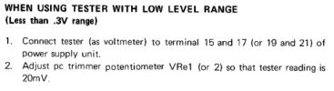
Then on page, after a page titled "Color Code", and with a copyright symbol, followed by "172-9 PRINTED IN JAPAN (T)" in the lower right, it says to, [when tester as ammeter, set pc trimmer pot (VRe1, 2) to minimum, Couple tester to collector of power transistor (Q3,4) and negative power supply lead. Adjust pc trimmer pot so that tester reading is 20mA.] AND, below that, it says, [when using tester with low level range, connect to terminal 15 and 17 (or 19 and 21) of power supply unit. Adjust pc trimmer pot VRe1 (or 2) so reading is 20mV]. It includes "THE SIMPLIFIED CIRCUIT": [Total resistance is R=Rk2 + Rk4 divided by 1 ohm] (Rk1, 2, 3, and 4 are .47 ohm, so adding two equals approximately 1 ohm) [Bias current (I) is 20mA. The voltage drop can be found from Ohm's law. V = I X R = 20 mV].
The [ and ] indicate where the wording is essentially directly from the manual and the ( and ) indicate what I have inserted.
I include screenshots.
Question is: Don't both of these adjust the Bias?
And, if so, which is the correct one?
AdjustmentOfAudioSection.pngAudioAdjustment_Bias.pngI am leaning toward the latter one using the terminals 15 and 17, and 19 and 21.

 
Thank you for the response. Do you think I need to worry about the 5mA difference between the Bias in Method 1 (15mV should equal 15mA) and Method 2 (20mV equals 20mA) causing an unwanted increase in the heat generated by these 52-year-old Power transistors?
 
Good troubleshooting so far. My 5002 has channel dropping out again from that damn balance pot, think it time to bypass it.

Looking at Kenwood bias guide it shows 10mA. Let unit warm up first to get to operating temperature. Measure across both emitter resistors per side.

.47 +.47 x 10mA = ~10mV

IMG_4617.png
 
Thanks again. I have seen those pages before, but just now understand what they were saying. Appreciate the help.
 
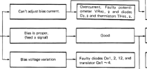
I have gone back to using my cheap set of speakers until I feel more confidence in this amplifier not flaming out. As discussed previously, I was working on getting a good Bias reading on the power transistors. When I had attempted to set it per the service manual, I was not able to see a setting that was steady. Using the trouble shooting section of the manual, I concentrated on "Can't adjust bias current". After replacing VRe1 and VRe2 with some multi-turn pots, recommended in another posting, I got some better readings, but the bias voltage continued to fluctuate (it also helps when you set the meter to measure DC, not AC). I then turned to the "Bias voltage variation" section, and replaced De1, De2, and De12. After replacing those I am able to adjust the Bias (after letting the amp run for a few minutes to warm up) to a wanted voltage and have it stay at that point. After the much-appreciated discussion with eizner23, I initially set the voltage on the emitter resistors (Rk1 and Rk3 for Q1 and Q3, and Rk2 and Rk4 for Q2 and Q4) to 18.8. The service manual says V = I * R, where the emitter resistors are .47 ohm and the document eizner23 posted shows a 10mA bias current for the KA-6004. This gives .94 ohms times .01A for 9.4mV. However, I was hung-up on where the service manual showed 20mV and had a brain freeze. The next day I realized I had doubled the current and set out to set it to the 10mA. Connecting my trusty Radio Shack multi-meter, and powering on the unit I saw the left channel (the one I think I believe has been working correctly since I first powered it on) was now upwards of 30mV. Of course, this was after not seeing any reading on my meter, changing the VRe1 and 2 settings to see if anything changed on the meter, powering down, changing batteries, checking voltage on another device, then realizing I had the meter set to AC, not DC. I then set the Bias voltage to 9.4mV, which should give me the 10mA Bias current. I am attaching 3 screenshots which may help in visualizing what I am boring you with.
BIAS_Issues.pngAdjustBiasPins15and17.pngD1D2andVRe1.png
Anyway, even with the cheap speakers the sound has really good balance and separation. The hi and lo filters appear to be functioning, as does the Bass, Treble, muting and loudness. I am going to replace the 4 large electrolytics on the power board, along with some smaller ones, and some 3 watt resistors which have some discoloration. After that I plan to run it on my Bose 401s while I finish repair on the 901s and then start on my 501s, an NEC A10II power amp, and a smaller Marantz 1060 AMP. Thank you.
 
I did want to add that the section, "Audio Adjustment [BIAS ADJUSTMENT]", which says "connect the voltmeter to the emitter resistor of power transistors" is the same as the latter one which tells us to use "terminal 15 and 17 (or 19 and 21) of power supply unit". Connecting to pins 15 and 17, or 19 and 21, is connecting across the emitter resistors of the emitters of the two transistors. Looking at the inserted screenshot, you will see the emitter of Q2 goes to pin 15 through Rk2, up through Rk4 and to pin 17 to the emitter of Q4. The same for Q1 to pin 21, Rk1, Rk3 to pin 19 and then the emitter of Q3.

4_Power_Transistors.png
 
Back
Top Bottom