selmafrog
Active Member
And. Just when you thought it was safe to go back in the water. I'm back. Couldn't do it. I wanted to power it on and listen to my 70's vinyl; just could not bring myself to do that without checking some voltages first. I start on the main amp board, and everything is looking good - then I get to the junction of Re24/Re26 which I think should be reading 0V, since the junction of Re23/Re25 is shown as 0V on the schematic. That leads me to the power board. From a post on this site about the power board on a KA-6004, I read this, "Measure the DC voltage at pins 16 and 20 on the same power board. They are the right and left channel outputs. If the voltage at these pins is low (less than 0.5V), the relay circuit is most probably in trouble. But if the voltage at any one of these pins is higher than 0.5V, the problem is within the power amplifier section."
I read pin 16 @-12.4mV (.0124 V), pin 20 @ 31.6mV (.0316 V).
This indicates an issue with Relay 1 (RL1).
When I read the resistance of the power amps to ground (with the Main Amp board removed) I get (using E for Emitter, etc.) from these pins on the power board (first reading is with the gnd lead of meter to gnd, 2nd reading is with pos lead of meter to gnd):
E Q2 pin 15 1.787M/O.L
...........pin 16 1.788M/O.L
E Q4 pin 17 1.789M/O.L
...........pin 18 0.0/0.0 (expected)
E Q3 pin 19 O.L/O.L
...........pin 20 O.L/O.L
E Q1 pin 21 O.L/O.L
I then take readings between the Emitter, Base and Collector - (reversing the leads on the PNPs) and when I reversed the normal leads on each transistor only Q3 showed a reading between Base and Collector of 213k. Q1/Q2 = npn, Q3/Q4 = pnp
Q1 E-B 2.215M E-C O.L B-C 2.037M Q3 E-B 2.670M E-C 2.74M B-C 98.5k
Q2 E-B 2.289M E-C O.L B-C 2.118M Q4 E-B 2.750M E-C O.L B-C 2.107M
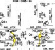
Looking at these reading makes me think it is time to change Q1-Q4 since Q3 appears weak, and the others are just as old with probably the same heat buildup during the years. I have a new relay I ordered from a German supplier several months ago, so I will change the relay to see if that has a positive effect while I wait to see if anyone has a different perspective on the issue. I am attaching a part of the schematic showing the Main Amp and Power Board - let me know if this violates any posting rules/policies.
I read pin 16 @-12.4mV (.0124 V), pin 20 @ 31.6mV (.0316 V).
This indicates an issue with Relay 1 (RL1).
When I read the resistance of the power amps to ground (with the Main Amp board removed) I get (using E for Emitter, etc.) from these pins on the power board (first reading is with the gnd lead of meter to gnd, 2nd reading is with pos lead of meter to gnd):
E Q2 pin 15 1.787M/O.L
...........pin 16 1.788M/O.L
E Q4 pin 17 1.789M/O.L
...........pin 18 0.0/0.0 (expected)
E Q3 pin 19 O.L/O.L
...........pin 20 O.L/O.L
E Q1 pin 21 O.L/O.L
I then take readings between the Emitter, Base and Collector - (reversing the leads on the PNPs) and when I reversed the normal leads on each transistor only Q3 showed a reading between Base and Collector of 213k. Q1/Q2 = npn, Q3/Q4 = pnp
Q1 E-B 2.215M E-C O.L B-C 2.037M Q3 E-B 2.670M E-C 2.74M B-C 98.5k
Q2 E-B 2.289M E-C O.L B-C 2.118M Q4 E-B 2.750M E-C O.L B-C 2.107M
Looking at these reading makes me think it is time to change Q1-Q4 since Q3 appears weak, and the others are just as old with probably the same heat buildup during the years. I have a new relay I ordered from a German supplier several months ago, so I will change the relay to see if that has a positive effect while I wait to see if anyone has a different perspective on the issue. I am attaching a part of the schematic showing the Main Amp and Power Board - let me know if this violates any posting rules/policies.