

You are using an out of date browser. It may not display this or other websites correctly.
You should upgrade or use an alternative browser.
You should upgrade or use an alternative browser.
DIY High or Low Ouput Moving Coil Phono Stage
- Thread starter HypnoToad
- Start date

FrankPA
Active Member
Here's a link to a simple build to get you started:
http://www.instructables.com/id/DIY-Lead-Acid-Battery-Charger/
http://www.instructables.com/id/DIY-Lead-Acid-Battery-Charger/

Frank,
Thanks, I'm copying that to a file.
Big Bill. You have PM/email.
Thanks, I'm copying that to a file.
Big Bill. You have PM/email.

WntrMute2
Super Member
Well, I just placed an order from Richard. Ordered a pair each of the VSPS 300 as well as the PhonoClones. Currently running HOMCs but want to experiment with LOMCs too. Added a few parts that the BOM confused me over. We'll see how I do. This will be my first build without step by step instructions. Which end of the soldering iron is hot?

nu2toobs
Can you here that?
I'm a "step by step guy too"Well, I just placed an order from Richard. Ordered a pair each of the VSPS 300 as well as the PhonoClones. Currently running HOMCs but want to experiment with LOMCs too. Added a few parts that the BOM confused me over. We'll see how I do. This will be my first build without step by step instructions. Which end of the soldering iron is hot?
 . I've built a Heathkit integrated amp with successful results, and I can read a schematic, but can't build off of one. A block diagram on the other hand is a little more comprehensive to me.
I've been thinking about using some of those 12 V sealed lead acid battery's to run my LOMC pre. Does anybody know where I could find a cheap battery charger circuit board with an auto charge/off feature that would work with them?
Don't know if you've seen this Bill, I just came accross it myself (half way down the page):
http://www.smcelectronics.com/emod.htm

Bluespower
Active Member
I've got some phonoclone boards coming as well. I've never built anything like this before but I do have two audiophile electrical engineering friends for moral support. Film at 11:00.

Well, I just placed an order from Richard. Ordered a pair each of the VSPS 300 as well as the PhonoClones. Currently running HOMCs but want to experiment with LOMCs too. Added a few parts that the BOM confused me over. We'll see how I do. This will be my first build without step by step instructions. Which end of the soldering iron is hot?
The hot end.
Just do everything in order, smaller to larger components, resistors first, then op amp sockets, small caps then large caps. Take your time and double check everything before you solder them on. and you will be fine.:thmbsp:

Big Bill
Summertime Rolls.....
Here is what I've decided....
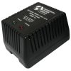
Hello guys and thanks for the links! I’ve decided to forgo the onboard battery charging circuit board. If I’m going to go the battery route then I don’t want any 60 cycle AC noise anywhere near the unit. I’ve purchased this "wall wart" charger from Flea-Pay which I’ll operate with a chassis mounted toggle switch:

I’ve also purchased two of these batteries from Flea-Pay which I’ll mount within the chassis:

Here are the battery specs:
This UB1213 is a sealed lead-acid (SLA) absorbed glass mat (AGM) rechargeable battery. AGM and GEL batteries are lead-acid and of the same battery chemistry (lead-oxide, lead sponge, and sulfuric acid electrolyte), but the electrolyte is stabilized differently. In AGM batteries, the electrolyte is suspended in fiberglass mat separators which act as absorbent sponges.
• Will not leak even in the upside-down position
• Non-hazardous material shipping under Class Code 60 IATA/FAA approved
• Resists shock and vibration
• Environmentally-friendly
• Lower self-discharge rate
• No gassing during charging (safer for enclosed applications with little venting)
• Maintenance-free, never needs filling
• Due to even distribution of electrolyte, plates remain covered avoiding dry corrosion
• Meets all EPA/OSHA marine requirements
• UL Recognized
• Dot 60 classified for easy transportation
• Reliable power for mission critical applications
Dimensions:
• 12 V
• 1.3 Ah
• L = 3.82”
• W = 1.69”
• H = 2.28”
• 1.21 lbs.
Here's a link to a simple build to get you started:
http://www.instructables.com/id/DIY-Lead-Acid-Battery-Charger/
Don't know if you've seen this Bill, I just came accross it myself (half way down the page):
http://www.smcelectronics.com/emod.htm
Hello guys and thanks for the links! I’ve decided to forgo the onboard battery charging circuit board. If I’m going to go the battery route then I don’t want any 60 cycle AC noise anywhere near the unit. I’ve purchased this "wall wart" charger from Flea-Pay which I’ll operate with a chassis mounted toggle switch:
I’ve also purchased two of these batteries from Flea-Pay which I’ll mount within the chassis:
Here are the battery specs:
This UB1213 is a sealed lead-acid (SLA) absorbed glass mat (AGM) rechargeable battery. AGM and GEL batteries are lead-acid and of the same battery chemistry (lead-oxide, lead sponge, and sulfuric acid electrolyte), but the electrolyte is stabilized differently. In AGM batteries, the electrolyte is suspended in fiberglass mat separators which act as absorbent sponges.
• Will not leak even in the upside-down position
• Non-hazardous material shipping under Class Code 60 IATA/FAA approved
• Resists shock and vibration
• Environmentally-friendly
• Lower self-discharge rate
• No gassing during charging (safer for enclosed applications with little venting)
• Maintenance-free, never needs filling
• Due to even distribution of electrolyte, plates remain covered avoiding dry corrosion
• Meets all EPA/OSHA marine requirements
• UL Recognized
• Dot 60 classified for easy transportation
• Reliable power for mission critical applications
Dimensions:
• 12 V
• 1.3 Ah
• L = 3.82”
• W = 1.69”
• H = 2.28”
• 1.21 lbs.
Attachments

Last edited:
I was just drawing what I thought might work for a charge/operate switch. For complete isolation from the charger during operation a four pole double throw switch is needed. I will sketch the connections, take a picture/scan and post it.
Hello guys and thanks for the links! I’ve decided to forgo the onboard battery charging circuit board. If I’m going to go the battery route then I don’t want any 60 cycle AC noise anywhere near the unit. I’ve purchased this "wall wart" charger from Flea-Pay which I’ll operate with a chassis mounted toggle switch:
This UB1213 is a sealed lead-acid (SLA) absorbed glass mat (AGM) rechargeable battery. AGM and GEL batteries are lead-acid and of the same battery chemistry (lead-oxide, lead sponge, and sulfuric acid electrolyte), but the electrolyte is stabilized differently. In AGM batteries, the electrolyte is suspended in fiberglass mat separators which act as absorbent sponges.
I am eager to hear your impressions once there up and running. Keep us posted.:thmbsp:
I was just drawing what I thought might work for a charge/operate switch. For complete isolation from the charger during operation a four pole double throw switch is needed. I will sketch the connections, take a picture/scan and post it.
I had that idea too, when in the off position it's charging? So you can't charge while it's operating.
I’ve also purchased two of these batteries from Flea-Pay which I’ll mount within the chassis:
This UB1213 is a sealed lead-acid (SLA) absorbed glass mat (AGM) rechargeable battery.
For those that want to give these a try but would rather avoid that auction site, here's a reliable source I've use many times...
http://www.allelectronics.com/make-...atteries-Rechargeable/Sealed-Lead-Acid/1.html
Big Bill
Summertime Rolls.....
I had that idea too, when in the off position it's charging? So you can't charge while it's operating.
Thats exactly right!:yes:

Fasterdamnit
Super Member
Op-amp rolling
Replaced the OP27's with some OPA134PA's. This is a worthwhile change. Bass is a bit deeper and bit tighter attack. Vocals are a tad smoother. Soundstage widened a bit. :thmbsp:
Digikey link--> http://search.digikey.com/scripts/DkSearch/dksus.dll?Detail&name=OPA134PA-ND
Replaced the OP27's with some OPA134PA's. This is a worthwhile change. Bass is a bit deeper and bit tighter attack. Vocals are a tad smoother. Soundstage widened a bit. :thmbsp:
Digikey link--> http://search.digikey.com/scripts/DkSearch/dksus.dll?Detail&name=OPA134PA-ND
Replaced the OP27's with some OPA134PA's. This is a worthwhile change. Bass is a bit deeper and bit tighter attack. Vocals are a tad smoother. Soundstage widened a bit. :thmbsp:
Digikey link--> http://search.digikey.com/scripts/DkSearch/dksus.dll?Detail&name=OPA134PA-ND
Great news, did you change all four?
Those OPA134PA's are cheap too.
The LME49710NA is supposed to be good as well.
It's hard to imagine these sounding any better, but there you go.:yes:
Last edited:
Fasterdamnit
Super Member
Yup.
Tried some mix and match but best sound was all 4. I bet the 49710's do sound good- You know how I like the 49720's
Tried some mix and match but best sound was all 4. I bet the 49710's do sound good- You know how I like the 49720's
Yup.
Tried some mix and match but best sound was all 4. I bet the 49710's do sound good- You know how I like the 49720's
I thought you might like them.
I am hankering to try some AD797's and OPA637's, and the AD843 which is pretty much the single circuit equivalent to the AD823.
I put some AD797's in the front end of a Parasound Z that I was modding and it sounded fantastic. They love low input impedance, if they are stable there is probably none better in the first stage.
I was just drawing what I thought might work for a charge/operate switch. For complete isolation from the charger during operation a four pole double throw switch is needed. I will sketch the connections, take a picture/scan and post it.
Well, I drew it up a four pole double throw switch and then realized it won't work. Well, not the way I drew it. And maybe not at all.
Then I just sat down and drew the connections that are needed in the "operate" and "charge" positions. I think it will require an odd switch. Maybe 8 poll double throw? My head hurts now I will have to think on it more.
Ok, I think I got it. 4PDT does it. If anyone sees a problem, Please let me know, I'm burned out today. Let's see if this posts...

Last edited: