• The move to the new server is done. There are some software and database maintenance updates in process. This has us passing the hat around to help out. We appreciate any donations. Seriously, even a dollar helps. The payment page may be found here - https://www.audiokarma.org/support.html

DIY High or Low Ouput Moving Coil Phono Stage

If you are going to charge the batts in series at ca 28V voltage/current limited a DPDT power/charging switch will do fine as the center rail need not be switched. A doubler off a smallish ca 12 AC wallwart with a series small incandescent light bulb and 14. somethingV zener across should work OK as the charger
 
Maybe even a switch with on-off-on. The off position meaning that it's neither on or charging, as the current draw is so low, charging will not be needed often?
 
Yep, & I have a few of those center-off switches for these projects and a couple of the little gel-cells ref'ed earlier on order. Just need a finalized version and a board with parts to stuff to go forth on this one.
 
Last edited:
Update.....

Hello gang, I’ve now installed the OPA134 Burr Brown’s in my Toad LOMC pre and the differences are profound. For instance, the bass response is up and the highs have smoothed out just slightly. This really isn’t a surprise to me as these are the mono versions of the OPA2134A Burr Brown’s that I like so much in my Bugle. I’ll perform another “shoot out” between this pre and the Bugle as promised once I’ve got all three pre’s mounted in the same chassis.

As for my “three pre” chassis project, the batteries and rotary selector switch (part number SWR 49C14931) have arrived but the charger and chassis haven’t. I’ve got a wiring plan in mind for the battery charging switch but don’t have Grainger’s diagram charting skills. I’ll have to figure someway to draw it out and upload it to this thread. I’ll be sure to post it once I have.


Bill.:thmbsp:

 
PIO, you are spot on about not needing the fore pole for series battery charging. I'm intending to use an existing charger, my Ack! dAck! charger, for this. So I will need the 4PDT.

Bill, hand drawn schematics are a time honored tradition in electrical. Napkins are used most often. I used AutoCad because it was handy. I figured it all out on paper just like anyone else would but then I wanted others to be able to understand my scratchings. You know if you let me know what you want I can get a copy of the wiring to you.

The DT Center Off alternative is good if you keep the charger on all the time but I will only charge when needed then swap it back over to my Ack!. The Ack! only gives the option of having the charger attached or playing. The switch also removes all connections to the AC line, i.e. all attachments to the charger least any noise should creep in (apologies to Fairport Convention's Long Lankin).

So now I need to find a connector that mates with this:
 

Attachments

  • IMG_0760[1].jpg
    IMG_0760[1].jpg
    46.7 KB · Views: 43
Last edited:
PIO, you are spot on about not needing the fore pole for series battery charging. I'm intending to use an existing charger, my Ack! dAck! charger, for this. So I will need the 4PDT.

The DT Center Off alternative is good if you keep the charger on all the time but I will only charge when needed then swap it back over to my Ack!. The Ack! only gives the option of having the charger attached or playing. The switch also removes all connections to the AC line, i.e. all attachments to the charger least any noise should creep in (apologies to Fairport Convention's Long Lankin).

So now I need to find a connector that mates with this:
 
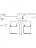
Grainger: Here is the circuit I have planned for my CNC pp. I have implemented the relay, so I don't have to worry about yet another switch to control the pp. The DPDT switch for the charger has not been added yet because I have not upgraded to rechargeable batteries.

attachment.php


Using an on-off-on switch will ensure that part of the battery circuit is not connected to the pp when you go to the charging mode, but it still depends on the operator to turn off the TT before the switch. Would be nice to have some mechanism to positively disconnect the pp before the connection to the charger is completed.


EDIT: I just noticed that the DPDT switch was dawn in wrong, so I have corrected it.

.
 

Attachments

  • CNC Batteries & Relay.JPG
    CNC Batteries & Relay.JPG
    37.3 KB · Views: 376
Last edited:
Hello gang, I’ve now installed the OPA134 Burr Brown’s in my Toad LOMC pre and the differences are profound. For instance, the bass response is up and the highs have smoothed out just slightly. This really isn’t a surprise to me as these are the mono versions of the OPA2134A Burr Brown’s that I like so much in my Bugle. I’ll perform another “shoot out” between this pre and the Bugle as promised once I’ve got all three pre’s mounted in the same chassis.

As for my “three pre” chassis project, the batteries and rotary selector switch (part number SWR 49C14931) have arrived but the charger and chassis haven’t. I’ve got a wiring plan in mind for the battery charging switch but don’t have Grainger’s diagram charting skills. I’ll have to figure someway to draw it out and upload it to this thread. I’ll be sure to post it once I have.


Bill.:thmbsp:

Bill, are you taking into account the acoustic absolute polarity inversion of the LOMC trans-impedance pre when comparing it to those that do not? It makes quick-shift comparisons very difficult as one must invert the cartridge lead connections to get the correct polarity with the TI pre. I do readily hear the difference and for me it is a sonic deal-breaker regardless of anything else going on.
 
Bill, are you taking into account the acoustic absolute polarity inversion of the LOMC trans-impedance pre when comparing it to those that do not? It makes quick-shift comparisons very difficult as one must invert the cartridge lead connections to get the correct polarity with the TI pre. I do readily hear the difference and for me it is a sonic deal-breaker regardless of anything else going on.

No I'm not. Its my understanding that isn't necessary with this particular design. :no:


EDIT: Just talked with Grainer and he confirmed that while the first op does invert, the second OP corrects said phase for output . :yes:
 
Last edited:
I think you may be right in fact. I haven't the skiz handy but now remember it would be the add-on version I speculated that would have the problem. I think this one does a flip in the 1st trans-impedance stage and again in the RIAA second stage, making it self-correcting and I therefore stand corrected. Carry on---. and do keep us informed.
 
In my haste to get a drawing up for Grainger I drew the DPDT switch in a non-function state in post #147. That is now corrected.

.
 
Thats really slick Steve! :yes: Can you post a charging scheme for this setup?


Bill.

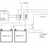
Per your request: This is a conceptual design, and there are a lot of caveats.

DISCLAIMER: I have not built or tested this charger design, so I must assume that it is not safe until it has been tested.

I do not know what charger you are using and whether or not it will safely charge your 2 batteries. This should be verified before you attempt to add the charger.

Relay and switch must be checked to ensure that they will carry the voltage and current required.

The control voltage from your TT must be able to activate the relay. Mine is a 24vdc relay, but it will work at voltages as low as 70% of that (16.8). B+ from my PL-570 is 20vdc.

The phono preamp will be on whenever the TT is on.

This design should keep the phono preamp separated from the charging circuit.

Charger must be wired such that it can only be turned on if this switch is in the "charge" position.

DPDT switches with an on/off/on configuration might be better than on/off, because the center position will ensure that the ground to the pp is interrupted before the charger is turned on.

attachment.php


This could also be done with a second relay but the charger would need to have a low voltage control line that the relay could handle. This would leave the charger on any time that the TT is off, so it is not an optimum solution. I would also want to see some kind of timing control added to preclude any conflict.

.
 

Attachments

  • CNC Batteries & Charger.JPG
    CNC Batteries & Charger.JPG
    48.9 KB · Views: 644
Steve,

Looks fine! This seems to be a 24V charging scheme, right? Wouldn't a third contact on the relay lift the circuit ground for charging and relieve the need for that contact on the DPDT switch at the lower right? Then all you would need is a SPST switch for the charger on/off control.
 
Steve,

Looks fine! This seems to be a 24V charging scheme, right? Wouldn't a third contact on the relay lift the circuit ground for charging and relieve the need for that contact on the DPDT switch at the lower right? Then all you would need is a SPST switch for the charger on/off control.

I believe you are correct, but I am not using rechargeable batteries yet.

NTE makes a 4PDT relay that will carry 2 amps. I think that you would be better off with a different style of relay. The PCB mount style would be a PITA to use with that many wires. Here are pics of my battery box. Gray cable is 4 wire bundle going to the CNC pp and red/brown TP is B+ connection from the TT. It was kinda tight putting 6 wires on this relay.

attachment.php


attachment.php


attachment.php


.
 

Attachments

  • 20179-.jpg
    20179-.jpg
    74.1 KB · Views: 287
  • 20181-.jpg
    20181-.jpg
    64.3 KB · Views: 291
  • 20182-.jpg
    20182-.jpg
    82.6 KB · Views: 292
Shoot you guys take the DIY thing and run with it - awesome! At some point I might have to try the Cube circuit, it looks like a very easy build.
 
I've been breaking in the Hypnotoad MC Phonostage with a Benz Glider MOMC for several days now and this thing is fantastic! Phillip was kind enough to give me this to try with my Glider in my system. What a guy! With the stock OPA27's I was getting more bass than I could handle (my QLS's get boundary reinforcement in my room) and the mid~highs sounded at bit 2 dimensional when compared with my Hypno-mod 640P~DV Karat.
Now, the 640P has AD823 and LM4562 opamps, so there aren't any Burr-Browns in the circuit. So today I swapped in a pair of AD797's for the OPA27's in the output stage (won't work in the inputs) and this preamp really came alive in my system! My vinyl has never sounded more "live" than this! Soundstage is deeper, instruments more separated and there's more 'air' in there! If you love the sound but it seems a bit too smooth in your system I recommend this tweak!

Disclaimer: I seem to have developed this opamp rolling sickness ever since Phillip modded the 640P. YMMV.

-Jim
 
Last edited:
Ok, I heard "Fasterdamnit's" two preamps today/tonight. We went out for a big burger in the middle of listening. Now I am half asleep and don't have my glasses on so my typing should be awful. (The post says 9:20 PM but it was 11:20 for me EDT, we go to bed early, up at 5:00 usually.)

The CNC just amazed me for a simple but extremely effective & inexpensive phono stage. I'm going to have to do some serious playing with it.

The LO/HO/MC phono stage has made my head swim. It is spinning, my head is. I should be asleep now but it isn't happening. My Denon DL-103C from 1986 is in pretty good shape and the preamp showed that. On the other hand the preamp showed itself off awfully well. The detail and dynamics are most impressive. The lack of noise allows us to hear the ebb and flow of the music on Love Over Gold.

Phillip, Jim was impressed enough with the Beatles Love album that he will be looking for one.

Something came to me, the resistor that matches the internal resistance of the MC cartridge is not critical. It is mainly used for lowering noise. It is also suggested it can be eliminated with the non-inverting input grounded.

I also haven't found the "formula" to calculate the feedback resistor that sets the gain for the first stage. There is a note on one of the RJM Audio pages stating it should be 180 times the internal resistance of the MC cartridge. But that doesn't take into account the output level of the cartridge. Can someone point me to the equation for Rf for the first stage taking the output and source resistance into account?

Thanks.

This will be a great and insanely inexpensive project with exceptional results.

And a big thanks to Big Bill for pointing this thread out to me.

Edit: I think Fasterdamnit will agree my 25+ year old Denon is still in good shape. I keep my stylus and LPs pretty clean. My personal opinion is that is a major factor in extended stylus and album life. (He will also tell you I'm not as fastidious as that sentence sounded.)
 
Last edited:
Back
Top Bottom