• The move to the new server is done. There are some software and database maintenance updates in process. This has us passing the hat around to help out. We appreciate any donations. Seriously, even a dollar helps. The payment page may be found here - https://www.audiokarma.org/support.html

Douk Audio Tube Amplifier Kit Assembly Advice Needed!

mfenberg

Well-Known Member
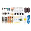
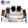
Hi all! I've had the fun pleasure of assembling electronic kits since the P-board offerings from Radio Shack! From there, I've assembled Heathkit and Dynaco kits in the 70's. I was even able to bring an HK A50K back to life, which I had posted on this forum. What they all had in common was that each and every one include pictorials to aid in assembly. While I can read a schematic, what I can't do is translate a schematic into a logical pictorial for kit assembly! So, there in lies my dilemma with my recently acquired Douk Audio "Hi-Fi Class A Single-Ended Tube Integrated Power Amplifier DIY KIT" from eBay.

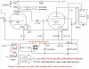
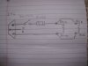
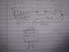
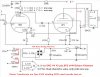
I just assumed (my first mistake!) that a reasonable pictorial would be included. Nope! Only a cryptic schematic...and showing only one channel at that! I contacted the seller and he quickly said he could send the instructions to my email address. What I received was pretty much what was already included in the "kit". See all the attached pictures.

I don't possess the skill to properly wire the components based solely on schematics! I guess I have a few options. One would be to see if any competent engineers on this forum would be willing to draw up a pictorial for me ( I would definitely pay you for your time) or should I just return the amp and call it a day?

I've even ordered a nice set of NOS Russian tubes for this amplifier! But, if I can't assemble this amp, what's the point?!!

Greatly appreciate any helpful advice from our AK members. Thanks in advance!
 

Attachments

  • 1.jpg
    1.jpg
    110.1 KB · Views: 312
  • 2.jpg
    2.jpg
    101.3 KB · Views: 267
  • 4.jpg
    4.jpg
    97.6 KB · Views: 258
  • 5.jpg
    5.jpg
    92.7 KB · Views: 280
  • 7.jpg
    7.jpg
    96.6 KB · Views: 337
  • DJ017.jpg
    DJ017.jpg
    199.6 KB · Views: 373
Register to hide this ad
Those are the skimpiest directions I've ever seen. That being said, you do have a picture to go off of with a schematic. Look up and download the data sheets for the tubes. This will help you know where to solder what to the sockets. Start with connecting all switches, jacks, tube sockets, power socket, tag strips, transformers, etc.
Then do one circuit at a time. Wire the tube heaters first, then power supply including power socket and power switch, resistor, bridge rectifier and filter caps. Then start adding components and wiring for the driver stage, then power tubes. Just take it slow and recheck your work. If your not comfortable doing that maybe there is an AK member close by that can help.
 
As Lavane said, the tubes datasheets

Then that will be clearer to you where to solder where.

The tubes pinout is see from the bottom, not from the top of the sockets.

So you start under the amp, from the guide , count clockwise pins 1,2,3,4,5,6,7,8,9

So for inputs, you use the grid #1 and grid #2 of the 6N2 (g1 and g2)

For the outputs of the 6N2 driver tube to go to the output tube, you use the Anode (plate) #1 and #2 (a1 and a2)

Down it is the cathode that goes to a feedback loop via a 18k resistor to the 8 ohms output and a 2k resistor to ground.
 
Last edited:
heh, yeah thats not much to go on. This is the kind of thing that someone who has a fair bit of experience building things from their own designs can manage, but its not what I'd consider a "kit" in the traditional sense.


inclined to agree with @Lavane though. Mount the hardware first and go from there. Just bolting things in place will reduce the pile of parts considerably and it will all begin to make a lot more sense at that point.

Schematic does give pinouts. The 6P1 are going to be the same on both sides. The 6N2 is a dual triode, so one channel uses pins 1,2,3, the other side uses 6,7,8. With the tube socket in place you'll see which side should use what just because the pins will be in the general direction of where the parts need to go. Nothing should cross side to side at that point.
 
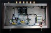
Thanks for everyone's help so far! Good, so it's just not me that believes the included schematic is not much to go on...especially for those, like myself, that don't deal with electronic schematics that much! As suggested, I had already thought about installing the hardware as a starting point, but once I do that, I can't return the unit. Granted, the parts count (resistors, capacitors and diodes) is not that great, which does help. And, yes, there is a reasonable picture of the underside showing how many of the components are connected. Still, it's not too detailed and is on the small side. As to the tube pinouts, I searched that before even posting for help! I haven't really found a practical picture, with pin numbers, to make a realistic opinion is this would help me. What I haven't done yet is to find the pinouts for the Russian tubes, which may be easier to find. In the meantime, I sent the seller a message with my concerns and will wait for a response. I have a feeling that he/she isn't fluent in English and may not understand my issue with a "pictorial". I will keep all of you informed and, again, thanks for your help!
 
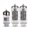
On the 3 tubes picture, the small signal tube is a Russian tube, a Voskhod "Rocket" 6N2P (6H2n Cyrilic), but the two 6P1 power tubes are Chinese tubes.
 
Last edited:
On the 3 tubes picture, the small signal tube is a Russian tube, a Voskhod "Rocket" 6N2P (6H2n Cyrilic), but the two 6P1 power tubes are Chinese tubes.
You are correct, sir! I hadn't even noticed that, nor have I checked the included tubes yet! I did just receive my Russian 6N2P-EB tube today and what's printed on the tube is exactly like what shows in the pictures. Sure hope I didn't waste money (not that it cost that much) on another 6N2 tube!
 
On the 3 tubes picture, the small signal tube is a Russian tube, a Voskhod "Rocket" 6N2P (6H2n Cyrilic), but the two 6P1 power tubes are Chinese tubes.
I just unwrapped the tubes. Yes, it includes a Russian Voskhod "Rocket" 6N2P as you pointed out! Well, at least the replacement I purchased was only about $11 and is the "EB" version. "E" for "long life" and "B" for "high reliability".
 
If he could send a hi resolution picture, that would be a big help to you.
Gadget stated how to read how the parts are connected to the 6N2 tube. Think of it as two tubes in one bottle. The schematic is showing one channel only.
So all the parts that connect to pins 1,2 and 3 are duplicated with pins 6,7 and 8 for the other channel. Once the power supply and heaters are wired up it does get easier to understand the rest. Having both channels in the schematic would have made it easier for you though.
 
You probably do have the skill - just don't realise it. Given the small number of components it won't be that hard and you'll learn a lot from it. I say get stuck in and have a go.
Thanks for the vote of confidence from everyone! I've already started to assemble the cabinet. Already running into issues! And, yes, some of the electronic components will be easy to install, but others will require more work based on just the schematic. I'll post more pictures along the way. This project isn't a priority for me, so not sure how long it will take. However, I'm determined to have it working! And, this "kit" sure makes me realize just how easy it was to assemble all my Heathkit and Dynaco kits!
 
Writing the instructions is arguably the hardest part of a proper kit. Add in a possible language issue and it gets even more difficult. The rest is just a pile of parts in a box, anyone can do that.
 
OK looking ahead a little bit. I assume you will wire this up for 110VAC, not 220VAC. If so, looks like the power transformer primaries, two sets of (Red - Black) are connected in parallel, ie both blacks tied together, both reds tied together.
Also, the schematic shows a 2 amp fuse, I didn't see any fuse in your parts picture. I think you will need to provide it if not included.
Also, the on-off switch in the schematic is not in the 'normal' location. Generally, the switch comes first, the fuse next, then to to transformer.
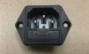
Again, one more item: It uses a IAC three wire connector for power connection. I believe the center blade is the 'chassis ground'.

The question for the community is:
Do you run with the third wire connected to the chassis, or is it best to run ungrounded to prevent ground loops? Comments?


Here's a rough sketch of what I think it will look like. Not clear from the pics where the components physically are located. Not sure if the transformer leads will reach the other components, I assume they will.

IMG_6025.JPG IMG_6026.JPG
 
Hi bg62!

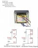
Your comments are well taken! Also, your pictorial is right on! I've already tested the transformer and wired it the way you said about tying the red and black together. The seller sent me an additional picture of the transformer wiring. It was as a document, so I converted it to a JPG to be able to attach it here.

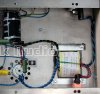
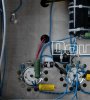
Concerning the third-wire ground, I was wondering the same thing! The transformer comes with a ground wire as part of the primary winding, yet it doesn't appear to be used! If you look at the picture showing the transformer mounted into the chassis, you can follow the path of this ground wire as it is wound around the high-voltage secondary wires...and appears to go nowhere!

I've also attached a picture of the IAC connector, which has a 2a built-in fuse. I've color coded the connectors...Red for "hot" and Black for "neutral". While the schematic shows that the ground lug isn't used, it would almost appear that the picture shows a neutral black wire connected to it. That doesn't make sense! So, yes, I'd also be interested to hear what the AK community has to say about this!

Forgot to mention this...the blue wire attached to the IAC is the "hot" (the kit comes with a large length of blue wire) and goes back to the power switch. It's interesting how the picture shows the way it's looped around all the other wires back to the switch!
 

Attachments

  • IMG_3685b.jpg
    IMG_3685b.jpg
    84.2 KB · Views: 101
  • IMG_3686b.jpg
    IMG_3686b.jpg
    77.8 KB · Views: 106
  • Xfmr_Wiring.jpg
    Xfmr_Wiring.jpg
    173.9 KB · Views: 131
  • Xfrmer_Wiring-2b.jpg
    Xfrmer_Wiring-2b.jpg
    60.6 KB · Views: 128
  • DJ017.jpg
    DJ017.jpg
    199.6 KB · Views: 122
Last edited:
Getting back to this whole "ground" thing, here are some additional pictures. It's too bad this forum doesn't allow for larger pictures!

You can see a ground lug attached to the chassis, secured to one of the screws that holds the output transformers. This lug was not included, so I'll look through my parts to see if I have one! Anyway, the blue wire goes from this lug back to the center (unused) lug for the 6N2 tube socket, which is then connected to pin 9, as per the schematic. All other grounding points that you see in the schematic appear to make use of this chassis ground, but I'm really not sure about the IAC connector.
 

Attachments

  • Chassis_Ground.jpg
    Chassis_Ground.jpg
    102.4 KB · Views: 105
  • DJ017.jpg
    DJ017.jpg
    199.6 KB · Views: 97
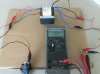
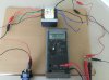
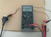
Here are the "no load" output voltages from the power transformer, showing the heater and high voltages.
 

Attachments

  • Heater_Voltage.jpg
    Heater_Voltage.jpg
    92.6 KB · Views: 75
  • Secondary_Voltage.jpg
    Secondary_Voltage.jpg
    90.1 KB · Views: 73
You can just ground the AC socket to the chassis. The high voltage will probably be ok, but the heater voltage is a little high. These Chinese kit amplifiers and even some finished equipment tend to get shipped with 110v transformers. Plugging them into 120v like we have bumps the voltage up some. Ideally you want 6.3v, +/- 5%. There are several ways to deal with the higher heater voltage.
A voltage dropping resistor, bucking transformer, etc. The 7.2v will work, but can shorten the life of the tube some. Scroll down in the link below and it discusses how to lower the heater voltage. It concerns a tube guitar amp, but still applies since line vtage was lower back when they were made. Someone may chime in on what's the best way to approach this. I just used a couple voltage dropping resistors in a phono preamp I had. It's a cheap, easy fix.
http://www.valvewizard.co.uk/heater.html
 
Hi Lavane! Thanks for weighing in on the heater voltage! I was thinking that the "no load" 7.2vac would be lower when the tubes are installed. But, if not, then the use of dropping resistors would be an easy fix. Thanks for the link, too! Obviously, I've still got a long way to go, but am hopeful that I'll emerge victorious!

Also attached is a picture showing my AC mains voltage.
 

Attachments

  • AC_Mains_Voltage-b.jpg
    AC_Mains_Voltage-b.jpg
    78.4 KB · Views: 47
Last edited:
Back
Top Bottom