• The move to the new server is done. There are some software and database maintenance updates in process. This has us passing the hat around to help out. We appreciate any donations. Seriously, even a dollar helps. The payment page may be found here - https://www.audiokarma.org/support.html

Douk Audio Tube Amplifier Kit Assembly Advice Needed!

Your line voltage may vary some from time to time. The last home I lived in it would drift between 119v to 122v. Here it stays steady at 120v. So if your house voltage goes up a bit, the heater voltage will be even higher. You can be with in +/- 10%, meaning as high as 6.9v and be within spec., but +/- 5% is optimal.
 
Yes. One of the mounting bolts for the power transformer will do. You can tie the circuit ground to it also.
I was pretty sure that's what you meant. Thanks for clarifying! As to the heater voltage, I could probably install wires for pins 4 and 5 for all three tubes, temporarily connect the transformer leads and measure the voltage to see if it has been reduced. If not, then dropping resistors will need to be calculated as to ohms and watts...something I'm not able to do!
 
Odd that you would say that since the Valvewizard link you posted recommends otherwise:

View attachment 2301903
Yes, I was going to go into more detail about how to connect 0V to mains earth but it could take a lot more explaining than I was prepared to do at the time so I just linked to someone else's article instead.
Basically, I don't recommend using the chassis as a convenient "it goes everywhere" earth wire that every 0V part of the circuit can be connected to. Keep the chassis tied to mains earth for safety. Keep the circuit 0V separate from the chassis, then tie 0V to the chassis via a resistor (possibly with a cap in parallel with it) so the case acts as a screen but earth loops will be avoided if another piece of equipment in the chain is also earthed.
 
Yes, I was going to go into more detail about how to connect 0V to mains earth but it could take a lot more explaining than I was prepared to do at the time so I just linked to someone else's article instead.
Basically, I don't recommend using the chassis as a convenient "it goes everywhere" earth wire that every 0V part of the circuit can be connected to. Keep the chassis tied to mains earth for safety. Keep the circuit 0V separate from the chassis, then tie 0V to the chassis via a resistor (possibly with a cap in parallel with it) so the case acts as a screen but earth loops will be avoided if another piece of equipment in the chain is also earthed.
Wow! All this is starting to go way over my head! How can I keep this build simple? I'm currently away from home and won't be able to have the amp in front of me until sometime on Sunday.

I really do appreciate all the help and input all of you have provided!
 
Just go slow, and one step at a time. It will start to make more sense as you go.
If you get stuck, or aren't sure what to do next, just ask, someone will be able to help. Take pictures with your phone as you go, it can be helpful also.
 
Just go slow, and one step at a time. It will start to make more sense as you go.
If you get stuck, or aren't sure what to do next, just ask, someone will be able to help. Take pictures with your phone as you go, it can be helpful also.
Thanks Lavane... greatly appreciated! Did you read my previous post where I mentioned about wiring up just the heater elements for all three tubes and checking the voltage? Would that be something reasonable to do to see if I'll need some dropping resistors to get the voltage closer to 6.3vac?
 
You can. If it stays that high, just don't leave them on too long. You want at leased 6.9v, no higher. I ran that phono preamp at around 7.2v for a few hours without Any problems. Honestly, there is probably a lot of equipment that has been running with those 110v transformers for some time now with out issue, yet. But it is hard on the heaters.
 
You can. If it stays that high, just don't leave them on too long. You want at leased 6.9v, no higher. I ran that phono preamp at around 7.2v for a few hours without Any problems. Honestly, there is probably a lot of equipment that has been running with those 110v transformers for some time now with out issue, yet. But it is hard on the heaters.
Thanks for letting me know! I should be able to try this sometime on Sunday and will report back.
 
I really prefer the heaters to not be above 6.7 but I think 10% (6.9v) is allowed per the tube manuals. In a perfect world they hang right at 6.3 but reality is what it is.
 
I really prefer the heaters to not be above 6.7 but I think 10% (6.9v) is allowed per the tube manuals. In a perfect world they hang right at 6.3 but reality is what it is.
Hi g73! Thanks for your input about this. I should have time on Sunday to try this out and will report back with the voltage readings.
 
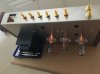
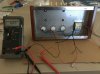
Ok...as promised, I just wired up the heater pins and installed the tubes. The transformer leads have not yet been soldered, but are securely in contact with pins 4-5. You can clearly see the warm glow from the tube heaters! The voltage is holding steady at 6.86vac, which is about .5v higher than ideal. Based on this, can any of you calculate what resistors I'll need, including wattage? I used the following link, http://www.valvewizard.co.uk/heater.html provide by AK member Lavane, and found what I needed under the topic "Dropping heater voltage". I'll attach each resistor to the socket closest to the transformer and attach the transformer blue wires to the resistors.
 

Attachments

  • Glowing_Tubes-1.jpg
    Glowing_Tubes-1.jpg
    71.6 KB · Views: 54
  • Heater_Voltage-1.jpg
    Heater_Voltage-1.jpg
    92.6 KB · Views: 55
Another thought. You might want to add a CL90 thermistor to the incoming power. I'd add it after the switch before the power transformer. It generates some heat, so space it away from other components. You can expect about a 2% drop in voltage, not great but on your 6.86 filament voltage, it would become 6.72 if my math is correct. Might make the 110VAC transformer feel better too. You would not see this reduction until you had the amp functioning, the heater current by itself is not enough to 'warm up' the CL90.
 
Another thought. You might want to add a CL90 thermistor to the incoming power. I'd add it after the switch before the power transformer. It generates some heat, so space it away from other components. You can expect about a 2% drop in voltage, not great but on your 6.86 filament voltage, it would become 6.72 if my math is correct. Might make the 110VAC transformer feel better too. You would not see this reduction until you had the amp functioning, the heater current by itself is not enough to 'warm up' the CL90.
Hi bg62! Based on your previous posted pictorial, I would hook the thermistor between the red leads from the transformer and the power switch, correct? The fuse is built into the supplied IEC connector.
 
Hi bg62! Based on your previous posted pictorial, I would hook the thermistor between the red leads from the transformer and the power switch, correct? The fuse is built into the supplied IEC connector.
Yes, and you could add one to each red lead and get 4% reduction to 6.58V.
 
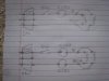
I would think either one or two wired as shown. I don't know how linear these are, so if you use two, I think you want each to see the full current load.IMG_6027.JPG
 
I would think either one or two wired as shown. I don't know how linear these are, so if you use two, I think you want each to see the full current load.View attachment 2303850
Yes, I was thinking how you have it wired in the lower picture. I'll go ahead and order two of them. Do you think I might still need some dropping resistors or will the thermistors be enough?
 
Back
Top Bottom