• The move to the new server is done. There are some software and database maintenance updates in process. This has us passing the hat around to help out. We appreciate any donations. Seriously, even a dollar helps. The payment page may be found here - https://www.audiokarma.org/support.html

Douk Audio Tube Amplifier Kit Assembly Advice Needed!

I don't know, I have to think that there is some safety margin on the tube filaments, overall unknown is with the incoming voltage, may be stable or may vary up and down 10 to 15 volts. Also I've no idea of the tube life filament degradation with an 'over voltage' condition. Probably depends on the tube and even within 'identical' tubes, I'm sure there's a variance. Personally, I don't think I've ever had a tube filament fail. I did have a bout with the power company when for a short period of time my incoming voltage hit 125.8 VAC and all my equipment is vintage. May have shortened my tube life, I have no evidence of that. Never owned a Chinese amp or any equipment that I recall designed for 110VAC. Even the 60 year old stuff was spec'd at nominal 117 VAC.
I trust Gadget on his recommendation to try to not exceed 6.7 V filament voltage.
If it was my amp, what would I do? I'd go with one or two CL90 and see what happens over time, but I don't mind working on these things.
 
Last edited:
Thermistors have long leads, so it's easy to mount them so they have some space around them. I have one I'm adding to an amp I'm building right now.
Two would probably be a good idea. One usually does it for me with older equipment made to run on 115v-117v. At leased your heater voltage isn't too high to begin with.
 

Attachments

  • 20210801_163000.jpg
    20210801_163000.jpg
    165.9 KB · Views: 28
I'm having to deal with German to English translations in my build. It has a high parts count and four different ways it can be built and use three different tube types depending on how the circuit is configured with different parts. I've had an easier time with Chinese translations. :biggrin:
 

Attachments

  • 20210801_163719.jpg
    20210801_163719.jpg
    170.6 KB · Views: 36
I'm having to deal with German to English translations in my build. It has a high parts count and four different ways it can be built and use three different tube types depending on how the circuit is configured with different parts. I've had an easier time with Chinese translations. :biggrin:
At least this comes with a circuit board! I would think that is much easier than some of the point-to-point soldering I'll be doing with many of the resistors and capacitors! Have fun with your build!
 
At least this comes with a circuit board! I would think that is much easier than some of the point-to-point soldering I'll be doing with many of the resistors and capacitors! Have fun with your build!
A little. I just bought a bare board to start with. I already had output transformers that will work. This one is a bit confusing though, in that there are so many ways to configure it. Depending on going with two class A designs, there is UL and pentode mode also. And depending on the output and driver tubes used certain parts and transformers have to be changed, omitted or put in different positions. The German terminology is a bit different also. It's been fun though figuring it out.
 
I'm going to order these off of eBay... https://www.ebay.com/itm/392925125475?hash=item5b7c299b63:g:m5AAAOSwXgxcU0Ph

In a previous post, I mentioned about installing one thermistor to each of the red leads. However, your pictorial shows one thermistor to each pair, red and black, correct?
Yes that is the correct CL90 , if using two, my second sketch is recommended. If you instead put one in each red lead, each thermistor would only see half of the total load and would not reduce the voltage as much. By putting them as shown in the sketch, each CL90 would see the total load and give a greater reduction.
 
I would think either one or two wired as shown. I don't know how linear these are, so if you use two, I think you want each to see the full current load.View attachment 2303850
Looking at this again, on the second sketch I show a CL90 in the neutral lead . This only feeds the transformer primaries. Does anyone see an issue with the CL90 in that leg?
Thanks,
Tom
 
One on each of the two primary leads, is that what you mean? I've seen it done that way also. Mosty you see just one right after the power switch. I've also seen two installed on the B+ secondaries. But that won't address the heater voltage.
 
One on each of the two primary leads, is that what you mean? I've seen it done that way also. Mosty you see just one right after the power switch. I've also seen two installed on the B+ secondaries. But that won't address the heater voltage.
Yes, I would like to get clarification with the use of two thermistors. I just ordered two CL90's and a set of ground lug terminals. Probably won't get them until the end of the week, so no real progress until then. I'll post other questions as they arise. Thanks everyone!
 
With two, just connect one to one leg of the power socket and one primary lead, then the other from the switch to the other primary lead. You can try just one first from the switch to one primary leg and see what your heater voltage is with just the one.
 
two in series on the same leg, one on each leg, its all the same as far as the transformer is concerned. It will get the same current and produce the same voltage drop no matter where it is.

The only thing I'm somewhat particular about with primary side wiring is that the fuse is the first thing on the hot wire, and the switch is the second thing. From there its just whatever it needs to be.
 
two in series on the same leg, one on each leg, its all the same as far as the transformer is concerned. It will get the same current and produce the same voltage drop no matter where it is.

The only thing I'm somewhat particular about with primary side wiring is that the fuse is the first thing on the hot wire, and the switch is the second thing. From there its just whatever it needs to be.
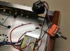
I just did a very crude mock-up of this, with some spare capacitors in place of the CL90 thermistors. As you can see, one thermistor will be attached to one red primary transformer lead. Both of the black primary leads are attache to the IEC neutral connector. The 2a fuse is part of the IEC. This is the wiring scheme I should use, correct?

I also plan to drill a hole in the chassis next to the IEC and install a screw to ground the earth terminal. There is a picture of this provided in link a recent reply by member rothwellaudio. Here's the link... http://www.valvewizard.co.uk/Grounding.pdf
 

Attachments

  • Thermistor_Wiring-a.jpg
    Thermistor_Wiring-a.jpg
    101.3 KB · Views: 51
Now I'm starting to wonder if I gave the right advice about going ahead and having a go at assembling this kit. Don't make a mess of the mains wiring or there could be tears - or worse. Hand on heart - do you know how to wire up a transformer?
 
no. Connect the two red wires together. If you're going to use a pair of thermistors, put them in series with the joined red wires. Running it like this, each thermistor gets half the current so half the voltage drop.
 
Now I'm starting to wonder if I gave the right advice about going ahead and having a go at assembling this kit. Don't make a mess of the mains wiring or there could be tears - or worse. Hand on heart - do you know how to wire up a transformer?
Hi rothwellaudio! Yes, I do know how to wire a transformer. This was just a quick mock-up to see how the thermistors should be connected. I did NOT power this up!!
 
no. Connect the two red wires together. If you're going to use a pair of thermistors, put them in series with the joined red wires. Running it like this, each thermistor gets half the current so half the voltage drop.
Wouldn't it just be better to use only one thermistor to deal with the AC inrush voltage and then use dropping resistors on the secondary filament leads to get closer to the ideal voltage of 6.3v?
 
The only thing I'm somewhat particular about with primary side wiring is that the fuse is the first thing on the hot wire, and the switch is the second thing. From there its just whatever it needs to be.
Gadget are you saying you prefer the fuse first,switch second. I think most vintage amps have the switch then convenience outlets, then fuse for the amp. (I know the OP's amp does not have convenience outlets). The OP's amp has the fuse built into the IAC connector.

As you can see, one thermistor will be attached to one red primary transformer lead.
No, go back and read that both reds need to be tied together, then the thermistor(s) after that.
 
Last edited:
Lots of vintage amps are wired in all sorts of silly ways. Mostly I just want the fuse before the switch so if the switch shorts out, the fuse might open to stop the problem. I don't have anything with switched aux outlets, so honestly I hadn't paid much consideration to that. I wouldn't run those through the fuse just because I wouldn't want to have to over-fuse the amp in order to make the outlets be able to carry some sort of useful current level.


Fuse in the IEC connector is just fine. The important thing is that it has a fuse somewhere and that if the fuse opens it will stop the power flow. Too many amps were built with no fuses at all, which I think is a terrible idea.

Wouldn't it just be better to use only one thermistor to deal with the AC inrush voltage and then use dropping resistors on the secondary filament leads to get closer to the ideal voltage of 6.3v?

you could, but if you do it on the primary side it also brings down the B+ at the same time. Thats a bigger consideration if the caps are run too close to their limits. No idea what this one includes.
 
Back
Top Bottom