• The move to the new server is done. There are some software and database maintenance updates in process. This has us passing the hat around to help out. We appreciate any donations. Seriously, even a dollar helps. The payment page may be found here - https://www.audiokarma.org/support.html

Douk Audio Tube Amplifier Kit Assembly Advice Needed!

Wouldn't it just be better to use only one thermistor to deal with the AC inrush voltage and then use dropping resistors on the secondary filament leads to get closer to the ideal voltage of 6.3v?
Personally, I would use dropper resistors to pull down the heater voltage if it needed it, and I wouldn't bother with the thermistor(s).
 
Personally, I would use dropper resistors to pull down the heater voltage if it needed it, and I wouldn't bother with the thermistor(s).
I mentioned that in post #17. I've gone that route with a couple Ch-Fi products using 110v primaries. Even with the higher voltage on the secondaries, the B+ wasn't too high, but the heater voltage was, and dropping resistors did the trick.
 
I mentioned that in post #17. I've gone that route with a couple Ch-Fi products using 110v primaries. Even with the higher voltage on the secondaries, the B+ wasn't too high, but the heater voltage was, and dropping resistors did the trick.
Maybe you could work with the OP to decide on the value of the resistor, type, wattage, maybe a quick sketch for installation, I'm sure he would appreciate that.
 
It wouldn't take much. I would start with two resistors somewhere around .25 to .33 ohms, 5 watt. One on each of the two heater wires.
20210804_080035.jpg
 
looks like heater current for a 6N2 is 340ma, and a 6P1 is 800ma (times two) for a total of 1.94 amps. If we're starting at 6.9 volts and want to be at 6.3 volts, 0.6 / 1.94 = 0.31 ohm drop resistor, or 0.33 is close enough. 0.6 V * 1.94 A = 1.2 watts, so a minimum of a 3 watt resistor would be appropriate here. Its going to get warm so keep wires away from it.
 
Personally, I would use dropper resistors to pull down the heater voltage if it needed it, and I wouldn't bother with the thermistor(s).
I found this good YouTube video...
...explaining about using thermistors with tube amplifiers. The sections I thought were most relevant begin at 4:06 (why use a thermistor), 9:29 (which thermistor to use) and 14:15 (how to use). I hope everyone interested will find some time to review this and comment on it. Thanks!
 
I found this good YouTube video...
...explaining about using thermistors with tube amplifiers. The sections I thought were most relevant begin at 4:06 (why use a thermistor), 9:29 (which thermistor to use) and 14:15 (how to use). I hope everyone interested will find some time to review this and comment on it. Thanks!
If you use dropper resistors on the heaters they will act as in-rush current limiters too.
What I don't much like about thermistors is that they're dissipating power all the time and dropping voltage. Ok, in your case you want to drop the voltage anyway.
Well, I'm only telling you what I would do, not telling you what you should do. Just be aware that my choice is an informed one.
 
If you use dropper resistors on the heaters they will act as in-rush current limiters too.
What I don't much like about thermistors is that they're dissipating power all the time and dropping voltage. Ok, in your case you want to drop the voltage anyway.
Well, I'm only telling you what I would do, not telling you what you should do. Just be aware that my choice is an informed one.
Thanks for this information! I was not aware that the dropping resistors would also act as in-rush current limiters as well. This amplifier "kit" is built on a fairly small chassis and I can see how using a thermistor might heat things up underneath! Definitely something to keep in mind!
 
looks like heater current for a 6N2 is 340ma, and a 6P1 is 800ma (times two) for a total of 1.94 amps. If we're starting at 6.9 volts and want to be at 6.3 volts, 0.6 / 1.94 = 0.31 ohm drop resistor, or 0.33 is close enough. 0.6 V * 1.94 A = 1.2 watts, so a minimum of a 3 watt resistor would be appropriate here. Its going to get warm so keep wires away from it.
g73! Thanks for doing the math for the dropping resistors and for letting me know that a 3 watt resistor will be sufficient. I'll order a pair today. Thanks again!

Will these work? https://www.ebay.com/itm/252977511552?hash=item3ae6a27c80:g:RmAAAOSwYlRZNuou
 
Thanks for this information! I was not aware that the dropping resistors would also act as in-rush current limiters as well. This amplifier "kit" is built on a fairly small chassis and I can see how using a thermistor might heat things up underneath! Definitely something to keep in mind!
That was kind my thinking on going with 5 watt dropping resistors instead of a 3 watt like gadget suggested. The 5 watt may not generate as much heat. But they probably will be physically larger than a 3 watt resistor.
 
That was kind my thinking on going with 5 watt dropping resistors instead of a 3 watt like gadget suggested. The 5 watt may not generate as much heat. But they probably will be physically larger than a 3 watt resistor.
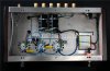
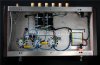
I'm seeing quite a few 5 watt ceramic resistors on eBay. In the attached picture, there would probably be sufficient room to mount them between the transformer and tube socket.
 

Attachments

  • 7.jpg
    7.jpg
    96.6 KB · Views: 62
I'm seeing quite a few 5 watt ceramic resistors on eBay. In the attached picture, there would probably be sufficient room to mount them between the transformer and tube socket.
Looking at the picture there is plenty of room. The 3 watt should work fine. There is plenty of space for heat to disapate.
 
3 watt would be the minimum, 5 watt would also be perfectly fine.

something I probably should have been clear about, thats 0.33 ohms total. If you want the heater string to be balanced, one 0.15 ohm per side would get it done. Those would need to be at least 2 watts each.
 
3 watt would be the minimum, 5 watt would also be perfectly fine.

something I probably should have been clear about, thats 0.33 ohms total. If you want the heater string to be balanced, one 0.15 ohm per side would get it done. Those would need to be at least 2 watts each.
Thanks for clarifying this! I've already purchased two of the .33 ohm resistors, so will just add them to my parts box! I'll go look for .15 ohm resistors now!
 
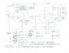
Hi all! Here's an update as of 8-6-21.

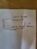
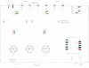
I took some time and drew out a pictorial of the hardware mounted in the chassis. I can use it to draw where the parts should go, based on the schematic. I can print out this pictorial as needed, if I make mistakes with wiring!!
 

Attachments

  • 7.jpg
    7.jpg
    96.6 KB · Views: 86
  • Douk_Schematic.jpg
    Douk_Schematic.jpg
    72.3 KB · Views: 88
  • Parts_Pictorial.jpg
    Parts_Pictorial.jpg
    39.6 KB · Views: 84
Remember when wiring the (-) grounds for the speaker terminals they should be connected to each other AND the chassis/earth ground. Did the kit come with a sheilded cable for the input jacks? If not, make sure you twist the wiring like the AC and heater wiring.
 
Remember when wiring the (-) grounds for the speaker terminals they should be connected to each other AND the chassis/earth ground. Did the kit come with a sheilded cable for the input jacks? If not, make sure you twist the wiring like the AC and heater wiring.
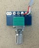
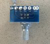
Thanks for pointing that out concerning the (-) speaker terminals. I believe I did notice this in both the pictorial and schematic. Concerning the shielded cable, yes, there is a small length included and I've already soldered it to the inputs of the volume control. From what I can see from the picture of the chassis, it appears that the shielded cable is only used from the input jacks to the volume control. From the control to the tube, it appears to be using only the included hookup wire.
 

Attachments

  • 7.jpg
    7.jpg
    96.6 KB · Views: 79
  • IMG_3723b-2.jpg
    IMG_3723b-2.jpg
    109.5 KB · Views: 77
  • IMG_3724b-2.jpg
    IMG_3724b-2.jpg
    109.1 KB · Views: 76
  • Douk_Schematic.jpg
    Douk_Schematic.jpg
    72.3 KB · Views: 72
Back
Top Bottom