

You are using an out of date browser. It may not display this or other websites correctly.
You should upgrade or use an alternative browser.
You should upgrade or use an alternative browser.
Douk Audio Tube Amplifier Kit Assembly Advice Needed!
- Thread starter mfenberg
- Start date
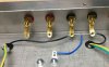
Is this what you're referring to? I just wired it up, but not yet soldered just in case I didn't get it right!Remember when wiring the (-) grounds for the speaker terminals they should be connected to each other AND the chassis/earth ground. Did the kit come with a sheilded cable for the input jacks? If not, make sure you twist the wiring like the AC and heater wiring.
Attachments

Lavane
Lunatic Member
Is this what you're referring to? I just wired it up, but not yet soldered just in case I didn't get it right!

Thanks! I'll solder it tomorrow!
8-11-21 Update regarding tube filament voltage.3 watt would be the minimum, 5 watt would also be perfectly fine.
something I probably should have been clear about, thats 0.33 ohms total. If you want the heater string to be balanced, one 0.15 ohm per side would get it done. Those would need to be at least 2 watts each.
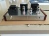
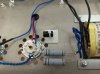
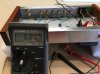
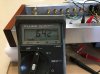
AK member "gadget73" recommended the use of two 0.15 ohm resistors, one on each leg of the 3.15v filament heater transformer wires. The resistors arrived yesterday and I did a voltage test before soldering everything together. I'm happy to report that the final filament heater voltage, with tubes installed, is 6.42vac with the resistors. That's just under 2% from the ideal 6.3vac! The voltage reading before the resistors is 6.84vac. It looks like I'm good to go! As you can see from the physical size, the resistors are 5w. Couldn't find a 3w, but there is room for these 5w resistors. You can also see that I lifted the ground wire from the primary side of the transformer, as it isn't required and I don't want to create hum issues.
I also tested the voltage with one CL90 thermistor connected to the hot lead from the IEC connector. It dropped the voltage below 6vac, so I will not be using it.
Attachments


I save them and I pick them up when I find them for small money. I've ended up with a nice little assortment of various sizes and shapes. They're available new too, couldn't spit out a part number right now but I think Keystone makes them and Mouser, Digikey, and the other usual sources sell them.
Lavane
Lunatic Member
I do buy them new from time to time when needed, adding them to an existing order. But sometimes I'm out of one that I need at the moment and I usually find one I need from what I've pulled.I save them and I pick them up when I find them for small money. I've ended up with a nice little assortment of various sizes and shapes. They're available new too, couldn't spit out a part number right now but I think Keystone makes them and Mouser, Digikey, and the other usual sources sell them.
Which resistors are you referring to? The voltage dropping resistors connected to the secondary blue wires? I need to look through my many boxes of accumulated parts over the years and see if I even have any terminal strips!I'd probably mount a terminal strip off that transformer ear to give a solid spot to connect the transformer leads to the resistors. I can see those moving and causing an issue.
8-13-21 Progress report!
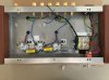
Here's where I'm currently at. As you can see, I keep my laptop open that shows the original Douk Audio chassis wiring scheme, along with the schematic. In addition, I update my pictorial as I add more parts. A lot of work, but I think it's worth it to compare the schematic against the pictorial. Slow and steady wins the race... I hope!!
Here's where I'm currently at. As you can see, I keep my laptop open that shows the original Douk Audio chassis wiring scheme, along with the schematic. In addition, I update my pictorial as I add more parts. A lot of work, but I think it's worth it to compare the schematic against the pictorial. Slow and steady wins the race... I hope!!
Attachments


Which resistors are you referring to? The voltage dropping resistors connected to the secondary blue wires? I need to look through my many boxes of accumulated parts over the years and see if I even have any terminal strips!
Yes.
Thanks for clarifying! Unfortunately, I don't seem to have any terminal strips around. But, those resistor leads are fairly stiff and I don't think there will be any issues with movement.Yes.

bjordan@sram
New Member
This is a great thread. I just got mine built, and I am really happy with the sound. I needed something to drive my Heresy speakers, and this fits the bill! This thread has been a great help.
-Brian
-Brian
Attachments

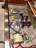

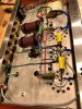


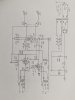
For those of you that have followed this thread, a big thanks to those that were instrumental to getting my Douk Audio amplifier up and running! Two big improvements were the use of a CL-90 In-rush limiter and the dropping resistors to get the AC heater voltage from 7.2v to 6.3v. Also grounding the AC input for safety. I see that our member, Brian, did this grounding as well! Finally, well after the fact, I stumbled upon this Layout+Wiring diagram! Really would have helped when I was starting out with the build! It's listed here to help future builders.
Attachments


knifeswitch
Active Member
What was it you were saying about you lacking the skills for this project. Not only did you have them but you sharpened them. Congrats and good threadFor those of you that have followed this thread, a big thanks to those that were instrumental to getting my Douk Audio amplifier up and running! .
I definitely sharpened my skills with this tube amplifier, thanks to this forum and its fine members who were there to help!What was it you were saying about you lacking the skills for this project. Not only did you have them but you sharpened them. Congrats and good thread