• The move to the new server is done. There are some software and database maintenance updates in process. This has us passing the hat around to help out. We appreciate any donations. Seriously, even a dollar helps. The payment page may be found here - https://www.audiokarma.org/support.html

dumptruck is finally building ewaves for real

It is treated for fire resistance, but my crossovers are staying external so that's not something I considered.

Thank you for replying to all my stupid questions. Regarding the fire-treatment, is this something that Bonded Logic does to the insulation or is that something that you applied?

Would it be possible to attach the insulation via staples or would you recommend glue? How "linty" is that stuff (will it create fiber puffs with air blowing in and out)?

I have a lot of questions about this stuff as I'm considering using it as well and have always read warnings about not using fiberglass in a ported cab.

100 lbs.? Damn!
 
Since it's insulation, it has to meet pretty strict fire standards and is treated with some kind of boron-and-things mix, which also discourages mildew/mold/moths. I have absolutely no idea what those standards are. Maybe you could use staples if you were using much thinner batts than I, but I'd rather not worry about them popping out. If you're worried about being able to remove it, it only takes a tiny bit of glue to tack it in place.

As for shedding, it's a lot like fiberglass: sheds quite a bit when you're messing with it, mostly in tiny wisps that you don't notice until they are all over you, but seems fine once in place. Warnings about fiberglass in ported cabs are rather baseless, IMO, but I also don't see any reason not to use this stuff instead if you can get it locally. It was only around $0.65/ft for the big bag of R13.
 
I built about six crossovers over the weekend. They were all pretty much the same in the end :rolleyes:. My latest PCD efforts:

New 7-component version, tested:
attachment.php


15 components, untested:
attachment.php


What does 15 components do, besides smoother HF?
- 1.1kHz crossover point without stressing the DE250 more below 1k.
- better phase alignment of drivers over a wider range (though you can't see it from the notch), and without inverting the HF
- much closer to ideal off-axis vertical behavior for this combo
- some wrangling of the 200-400Hz region that would hopefully make the midrange more neutral sounding. no getting rid of that pesky 550Hz dip, though.

Would it actually sound better? Beats me. I also found the briefly missing woofer resonance, which you can see is included here (ripple in woofer response over 1k).
 

Attachments

  • simpler1.gif
    simpler1.gif
    20.2 KB · Views: 247
  • complex4.gif
    complex4.gif
    20 KB · Views: 248
Nah, I am still struggling with establishing a reference level for the bass/midrange to base the rest of the response on, but I've been distracted learning about general crossover stuff and have not been working on that (plus the measurement computer died). It's about time I got back to it so I can get some more crossover parts ordered.
 
Last edited:
Home alone with a nasty cold last night, I put a new toy into the mix: a Rane AC22 (LR4 active crossover with delay). The main purpose was just to mess with the delay as a kind of sanity check for what I see in simulation, but I was also thinking about using the delay to free up the crossover design. I ended up trying out a hybrid crossover, with a 1.2kHz active, plus 1.5mH on the woofer and passive CD comp + an RLC notch on the highs. Despite being kind of sloppy, I think that may have been the best sound so far. The neat thing is that I can dial the crossover point from ~900-1600 with only minor changes in on-axis response, which I will be putting to use soon. Three other developments I haven't posted yet:

1. I am pretty convinced at this point that an on-axis response that gradually sinks ~4dB from midbass to 20kHz sounds the most natural. Similar to the Four Pi (http://www.pispeakers.com/Measurements/fourPi.html).

2. I am still concerned about the response between modal bass range and 1k. This has been a problem from the start. IMO, one of the biggest problems with home speaker DIY is measuring below 1k. That's where most of the fundamental notes in music are located, after all. Without reliable measurements, it is hard to separate the overall response trend under 1k from baffle step and bass issues, and then cabinet sound throws another wrench in the mix. All that said, I think the TD15 response is rising over its entire range, and countering that is tricky with a crossover point this high. Today, I'm going to see if I can find a place to measure lower frequencies without reflections in here. The AE measurement is not great, but it does appear to show a rise, much like I think I'm seeing and hearing:
td15m-sealedbox-measurements.png


3. I'm pretty sure I've gone back to the no-BSC side. Woofer break-in and tilted response made a pretty big difference. There may still be some lack of oomph at the height I want to place them, but I think I'll let subs/EQ take care of that. Too much inductance/resistance really seems to kill this woofer.

 
Last edited:
Well, I finished moving the measurement setup, and it does seem I can get a little bit cleaner data now. It also seems that this nasty 400-500Hz thing is real :(. There's a very similar thing in the AE bench measurement above, but not the ground plane ones as much... Hmm... EDIT: no, that's just floor bounce at 400Hz, I'm a dummy.

attachment.php
 

Attachments

  • new room measurement example.gif
    new room measurement example.gif
    51.7 KB · Views: 155
Last edited:
I forget, have you tried a low-Q 2nd order network yet on TD15M, to somewhat tame the rise before the actual crossover point? Active certainly is a good way to go and I really like my TD15M wired direct to the amp. Might have to dive into a passive though, as I'd like to upgrade my amplification and probably can't afford 4 channels of the good stuff. :) I'm also having issues measuring under ~1kHz in my room. I'm not too motivated to try anything until I get the phase plugs anyway.

az
 
Well, the problem I'm having with that idea is that the response dips a bit right before 1k, and a high Q network is actually a nice fix for that, whereas a low Q makes it worse. I'm still just not sure what's going on down there. This is what I was last listening to today (more hybrid active/passive madness), which seems pretty decent. It would be better if I had more resistors on hand. The acoustic slopes are nearly 40dB/octave!

attachment.php
 

Attachments

  • active2.gif
    active2.gif
    17.7 KB · Views: 149
Having some trouble installing the woofers (not unusual for me - I'm a terrible woodworker). The currently installed woofer went in pretty well, but one screw expanded the plywood on the roundover, cracking the finish. With eight screws and the heavy rubber gasket, the mount is plenty secure, but I'll have to fix that for cosmetic's sake.

Figuring "if it happened once", I tried mounting the other woofer on the other baffle, which is still free from the cabinet. This time three screws split the finish nearby, Yikes. So, I fixed the wood and the finish and tried it again. This time, no cracking but four screws stripped. :sigh:. It's probably safe to assume that if I add some material to the holes or fill and re-drill or whatever, I'll just crack it again. Time to come up with something else, I guess..

Not sure what.. The roundover won't allow for anything on the face, at least not in an obvious way. I guess I could try those insert things?

Too deep is not a good idea for a roundover, but you don't want the screws holding this 28lb woofer to be only 0.125" deep in the material OTOH. I think I have mine ~0.5" into the 0.75" baffle. Pre-drilled only very tiny holes, maybe 0.0625", so as to avoid stripping.

az
 
I'm afraid I could spend an eternity trading stripping for splitting and back again :D. It wouldn't actually be that hard for me to convert this to a flush mount, if it comes to that. It will muck up my time alignment, but I seem to have given in to active delay on the woofer already anyway.
 
I just finished and am taking a break. I'll go down and clean up before taking pix. I'll post a new thread in the speaker forum tonight.
 
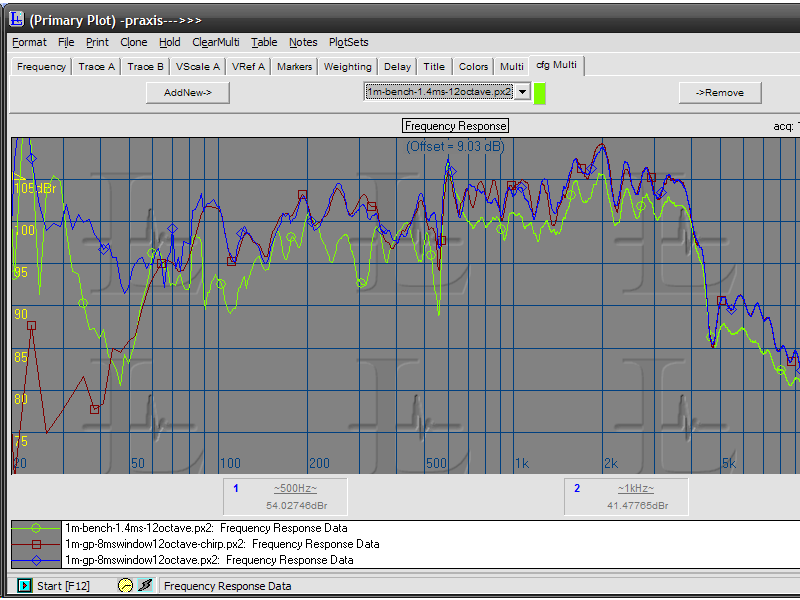
Here is a measurement of what I'm pretty sure this is the best sound I've achieved so far. LF is active, HF is active plus passive CD-comp. and a broadish passive notch at ~1400Hz. Measurements are accurate above approx. where the vertical yellow line is. I believe the bass actually levels off at what is 110dB on this graph:

attachment.php


The acoustic slopes end up like 5th order Bessel on the woofer and 6th order Bessel on the tweeter, not quite at the same point. In other words, there ain't much overlap. I will be trying a 2nd notch on the 2.5k peak to see if that's audible at all.
 

Attachments

  • active2.png
    active2.png
    44.7 KB · Views: 228
Oh, I forgot to mention a neat thing about that crossover: the CD-comp resistor functions like a broad EQ centered around 3kHz.
 
Since several folks have been asking about an all-passive crossover, here is one you could try. It is untested and quite expensive, so do it at your own risk. I am confident that it will work as designed, but it is a little bit different than what I've been listening to. Woofer must be rear-mounted, and listening axis is with the front-middle pointed right at you.

attachment.php
 

Attachments

  • passive 7_1.png
    passive 7_1.png
    31 KB · Views: 169
Thanks!

What effective baffle thickness did you end up with? Looking at the photos the waveguide is flush mounted and the woofer is rear mounted so I'm guessing 3/4" between front of the woofer frame and the rear of the waveguide flange.

Would using electrolytic caps on the woofer be a problem? They are almost free. Though it does seem a little pointless to save $ on the crossover for $400 of drivers :yes:
 
Back
Top Bottom