• The move to the new server is done. There are some software and database maintenance updates in process. This has us passing the hat around to help out. We appreciate any donations. Seriously, even a dollar helps. The payment page may be found here - https://www.audiokarma.org/support.html

Dynaco Dynakit St-70 rebuild thread

hrtattckcity

AK Subscriber
Subscriber
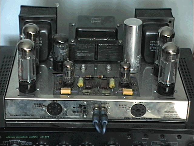
starting a thread to document an st-70 rebuild. I welcome all comments and advice. The intent is to generally refurb the unit to as close to stock as is cost effective and durable—I have read through the Gillespie baseline article and will most likely switch to SS rectifier per his recommendation, and replace the selenium rectifier, and probably use 6gh8a adapters in the 7199 sockets to keep cost down.

Thanks to @BillWojo for hooking me up with Kevin (whose handle I don’t know, but gave me a good deal on two st-70’s at the philly area meet) and CR for helping me out with the rebuild.

I’ve started a parts list, and I’d love some help verifying missing values.

I’d also love a link to a good thread on the selenium rectifier replacement.

If anyone had experience putting 6gh8a’s with adapters in place of 7199’s and can tell me if this is satisfying I’d also love to hear it.

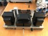
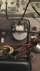
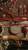
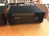
So far, I’ve just cleaned up the rusty transformers in situ with rust converter and lacquer; before and after attached.

Parts list to follow.
 

Attachments
  • 1EE67826-B970-44DD-B4B1-74A13E325AA8.jpeg
    1EE67826-B970-44DD-B4B1-74A13E325AA8.jpeg
    81.8 KB · Views: 209
  • B969D0C3-8178-4107-8DB1-B8E407495471.jpeg
    B969D0C3-8178-4107-8DB1-B8E407495471.jpeg
    77.2 KB · Views: 193
  • 1996B68B-7D3C-410C-9F9F-5344154FBE14.jpeg
    1996B68B-7D3C-410C-9F9F-5344154FBE14.jpeg
    86.7 KB · Views: 200
  • CF21B27A-65E1-43AA-8D0E-9D2D1DDFEDB0.jpeg
    CF21B27A-65E1-43AA-8D0E-9D2D1DDFEDB0.jpeg
    68.2 KB · Views: 196
Last edited:
Register to hide this ad
You can polish the chassis to a near mirror finish with a chrome cleaner like Flitz.
Have fun!
 
Kevin is @kve777

I'm guessing you bought the stock ones then? I recall he had 3 there, one was modified with a fancypants cord and the others looked original.
 
Look underneath at the bias pots and see if you can get the date of manufacture...of the pots
 
Kevin is @kve777

I'm guessing you bought the stock ones then? I recall he had 3 there, one was modified with a fancypants cord and the others looked original.

I bought the two stock ones--I have a friend who is interested in the second one, but I think we may rebuild one first and see how it goes.
 
Parts list below,
if anyone can verify the voltage rating of the 82pf silver mica capacitor, and the wattage of all the resistors under the chassis i would appreciate it.
List derived from Bob Latino's marked up image on the dynaco forum (attached with my notes on it as well) and the diagram and parts list from the manual. (update: pcb image fixed so that values are legible)

PCB
.1 to
.22uf (400 or) 600v need 4 orangedrop or film
.05 to .1uf (400 or) 600v need 2 orangedrop or film
390pf 500V MIN need 2 silver mica
82pf 1000v min need 2 silver mica
270k 1w need 2 metal film
47k 1w need 4 metal film
18k 1w need 2
18k 1/2w need 2
47 ohm 1/2w need 2
10 ohm 1/2w need 2
270k 1/2w need 4
620 ohm 1/2w need 2
1000 ohm 1w need 2
1.5 meg 1/2w need 2
330k 1w need 2

Chassis

50uf 75v need 2 electrolytic (have 47uf/100v nichicons but radial)
quad cap 80/40/30/20 525v or 30/20/20/20 525v
2x .02uf ? dual disk ceramic capacitor
15.6 ohm ? need 2 ?
1000ohm ? need 4 ?
10k ohm ? need 2 ?
470k ? need 2 ?
10 ohm ? need 2 ?
6.8k ? need 1 ?
22k ? need 1 ?
selenium rectifier--replace with diode--1n4007?
ss rectifier and 2 50ohm 10w resistors?
Adapter - use 6GH8A Instead of 7199 tube, 6GH8A Included need 2
el34 need 4

misc

new rubber feet
new mono/stereo switch
new fuse holder or cap for fuse holder
 

Attachments

Last edited:
Look underneath at the bias pots and see if you can get the date of manufacture...of the pots

Can you decipher those codes?
 

Attachments

  • E46BE442-898F-431A-ADBA-41E13136660D.png
    E46BE442-898F-431A-ADBA-41E13136660D.png
    310.4 KB · Views: 118
  • 88F38E2B-0502-461C-BEDC-1051D13576F3.png
    88F38E2B-0502-461C-BEDC-1051D13576F3.png
    335.2 KB · Views: 112
Both cages were pretty rough so I used the same rust converter as on the transformers.

Probably profane to paint the original brown cage black but it looks much sharper now.
 

Attachments

  • 94FE3E75-48A5-4F5A-B929-1D3B65A4EFDC.jpeg
    94FE3E75-48A5-4F5A-B929-1D3B65A4EFDC.jpeg
    98.9 KB · Views: 88
  • 7F3E4494-D058-44C5-A16F-206D179D7976.jpeg
    7F3E4494-D058-44C5-A16F-206D179D7976.jpeg
    104.6 KB · Views: 84
Looks pretty good! If you haven't seen it already, I suggest taking a look at the restoration article I wrote awhile back. Pretty much outlines what you said above, keeping the amp(s) in the stock configuration albeit with modern parts. I didn't bother replacing any of the resistors, though the larger value ones can be prone to drifting. Here are a couple of pictures of my amp:
st70_1.jpg

st70_3.jpg

With regards to the codes on the pots, they use the seven digit EIA system where the first three digits indicate the manufacturer, and the last four indicate the date of manufacture in the format YYWW. For the one with the red circuit board, the code appears to indicate the 21st week of 1960, and the one with the green board (like mine) looks to have been made in the 27th week of 1974. Anyway, good luck!
-Adam
 
Also replaced the speaker connectors using a kit I bought on eBay, although you can make your own if you have some PCB material.

You may have noticed the transformer is a little taller. It's from an Eico ST-70. It runs cooler and the B+ voltage is lower (although that spec is supposed to be the same) and is a bolt-in replacement,

DSCF1930.JPG
 
Parts list below,
if anyone can verify
- the wattage of all the resistors under the chassis
-voltage of the ceramic caps
-is there anything special about the 15.6 ohm bias resistor?


i would appreciate it

PCB
.1 to
.22uf 600v need 4 orangedrop or film
.05 to .1uf 600v need 2 orangedrop or film
390pf 500V MIN need 2 silver mica
82pf 1000v min need 2 silver mica
270k 1w need 2 metal film
47k 1w need 4 metal film
18k 1w need 2
18k 1/2w need 2
47 ohm 1/2w need 2
10 ohm 1/2w need 2
270k 1/2w need 4
620 ohm 1/2w need 2
1000 ohm 1w need 2
1.5 meg 1/2w need 2
330k 1w need 2

Chassis

50uf 75v need 2 electrolytic (have 47uf/100v nichicons but radial)
quad cap 80/40/30/20 525v or 30/20/20/20 525v
2x .02uf ? dual disk ceramic capacitor
15.6 ohm ? need 2 ?
1000ohm ? need 4 ?
10k ohm ? need 2 ?
470k ? need 2 ?
10 ohm ? need 2 ?
6.8k ? need 1 ?
22k ? need 1 ?
selenium rectifier--replace with diode--1n4007?
ss rectifier and 2 50ohm 10w resistors?
Adapter - use 6GH8A Instead of 7199 tube, 6GH8A Included need 2
el34 need 4

misc

new rubber feet
new mono/stereo switch
new fuse holder or cap for fuse holder


Parts list below,
if anyone can verify the voltage rating of the 82pf silver mica capacitor, and the wattage of all the resistors under the chassis i would appreciate it.
List derived from Bob Latino's marked up image on the dynaco forum (attached with my notes on it as well) and the diagram and parts list from the manual.

PCB

.22uf 600v need 4 orangedrop or film
.05 to .1uf 600v need 2 orangedrop or film
390pf 500V MIN need 2 silver mica
82pf 1000v min need 2 silver mica
270k 1w need 2 metal film
47k 1w need 4 metal film
18k 1w need 2
18k 1/2w need 2
47 ohm 1/2w need 2
10 ohm 1/2w need 2
270k 1/2w need 4
620 ohm 1/2w need 2
1000 ohm 1w need 2
1.5 meg 1/2w need 2
330k 1w need 2

Chassis

50uf 75v need 2 electrolytic (have 47uf/100v nichicons but radial)
quad cap 80/40/30/20 525v or 30/20/20/20 525v
2x .02uf ? dual disk ceramic capacitor
15.6 ohm ? need 2 ?
1000ohm ? need 4 ?
10k ohm ? need 2 ?
470k ? need 2 ?
10 ohm ? need 2 ?
6.8k ? need 1 ?
22k ? need 1 ?
selenium rectifier--replace with diode--1n4007?
ss rectifier and 2 50ohm 10w resistors?
Adapter - use 6GH8A Instead of 7199 tube, 6GH8A Included need 2
el34 need 4

misc

new rubber feet
new mono/stereo switch
new fuse holder or cap for fuse holder
 
Last edited:
-is there anything special about the 15.6 ohm bias resistor?
The original was a special non-inductive resistor with a tolerance of 1%. If the original still measures within tolerance, it doesn't need to be replaced. If it's gone out-of-tolerance (or burned up for some reason), a proper replacement is sold by Dynakit Parts.
Dynakit Parts (and possibly other sources as well) sell an up-rated version of both can capacitors which have a voltage rating of 550V (surge rating of 600V). Not as crucial to have the uprated can in a ST-70 versus the Mark II or III, but it's an option.
-Adam
 
Do note that using Si rectifier for B+ the voltages in the schematic will be grossly higher for a second or two after power on, 'A' will become close to full 425V until cathodes have been heated. Thus 400V is NOT enough for
coupling caps, 630V is what the doctor recommends.
Also do not increase or change values haphazard, it won't improve the amp it might even cause instability.
 
Is this not more of a concern when simply dropping-in two solid state diodes, and nothing more, to replace the tube rectifier?

But, he is planning to use two 50Ω 10-watt resistors as part of a solid-state B+ rectifier setup (post #13). Does this not duplicate the voltage drop of the 5AR4? And, wouldn't a CL80 thermistor, in series with the power transformer primary, slow startup and help to prevent the voltage from rising too high?
A tube rectifier don't start work until it's cathode is warm. Si rectifiers starts immediately, 100ohm in series don't make any difference as the tubes don't draw any current until several seconds later.
 
Suggestion,
If you were going to use the tube adaptors anyway, you could buy a new PCB made for those tubes (probably for the cost of the adaptors (stock design) it gets you away from the original pcb which is something of a weak link (not from design, they just made crappy Pcbs back then).
They tended to absorb moisture and most I've seen looked pretty cooked today.
 
Suggestion,
If you were going to use the tube adaptors anyway, you could buy a new PCB made for those tubes (probably for the cost of the adaptors (stock design) it gets you away from the original pcb which is something of a weak link (not from design, they just made crappy Pcbs back then).
They tended to absorb moisture and most I've seen looked pretty cooked today.

Yeah, I considered this--from AES the tube adapters with tubes are almost the cost of the dynakitparts 6gh8a version of the pcb3.
But are purists still tracking down 7199's--and is there value in holding on to backwards compatibility here? OR does everyone tend to agree the 6gh8a is a suitable replacement?
 
As i understand it , we're scraping the barrel for 7199s. Finding quiet ones is near impossible. (i'm sitting on a half dozen from before i owned an ST 70. Actually not sure how quiet they are). I rebuilt mine with a stock reissue board (7199) If i knew then what i knew now, i would have used the 6GH8 version. Dave has made tests and claims the 6GH8 works fine in an ST70 (not true for everything.) Otherwise my build follows Dave's baseline article. Sonically i don't think there's a difference between the 2 tubes. I'm not that far from you if you want to come by. I could demo both tubes. I have adapters and 6GH8s on hand
 
Silicon diodes start immediately, that is true, hence the suggestion for using a CL-80 or other suitable thermistor to ease startup and presumably avoid an over-voltage situation.

The 50Ω, 10-watt resistors would drop the voltage to the same level as if the 5AR4 were in use, under normal operating conditions and after warmup. Node "B" is specified at 375 VDC that proceeds to drop across the 47KΩ at the phase inverter's plate before reaching the 0.1µF coupling capacitors. I would think the 0.1µF coupling capacitors see significantly less than 375VDC under normal operating conditions and after warmup.

Have you or anyone actually measured how high the voltage goes at the 0.1µF during an immediate startup scenario? I wonder if it drops low enough across the 47KΩ that it would not exceed the 400VDC rating for the coupling caps even during an immediate startup like you'd get with silicon diodes replacing the 5AR4.
The other side of the coupling cap has negative bias , so the voltage comes above or close to 400V
Why take the chance ? 630V 0.1uF caps are not expensive. Tubes and transformers are much more expensive.
 
SS rectifier:
I was just going off the Gillespie baseline article when I mentioned the 50 ohm 10 watt resistor,
("To do a good job of mimicking the voltage drop of a GZ34 tube, there should be a 50 ohm 10 watt resistor installed BETWEEN the output of the SS rectifiers, and the FIRST filter cap. Installing a resistor at this location will control the peak currents drawn and improve regulation, providing nearly the same B+ level that a GZ34 would under any condition of operation. Installing a resistor after the first filter cap, would hurt regulation, and NOT limit the peak currents drawn from the power transformer.")
If I am using a plug-in tube socket SS rectifier like the ones available at AES (https://www.tubesandmore.com/products/solid-state-rectifier-yellow-jackets-yjr-5ar4-5u4-5y3) do I need this additional resistor and where specifically should it be located?


updated parts list:

PCB

.1 to .22uf 600v need 4 orangedrop or film
.05 to .1uf 600v need 2 orangedrop or film
390pf 1000v need 2 silver mica
82pf 500v min? need 2 silver mica
270k 1w need 2 metal film
47k 1w need 4 metal film
18k 1w need 2 metal film
18k 1/2w need 2 metal film
47 ohm 1/2w need 2 metal film
10 ohm 1/2w need 2 metal film
270k 1/2w need 4 metal film
620 ohm 1/2w need 2 metal film
1000 ohm 1w need 2 metal film
1.5 meg 1/2w need 2 metal film
330k 1w need 2 metal film

Chassis

50uf 75v need 2 electrolytic update to 100uf/100v
quad cap 80/40/30/20 525v or 30/20/20/20 525v
2x .02uf ? dual disk ceramic capacitor
15.6 ohm 3w need 2 wirewound
1000ohm 1/2w need 4 metal film
10k ohm 1w need 2 metal film
470k 1/2w need 2 metal film
10 ohm 1/2w need 2 metal film
6.8k 1w need 1 metal film
22k 1w need 1 metal film
selenium rectifier--replace with diode--1n4007--2 terminal strip
ss rectifier and 2 50ohm 10w resistors?
Adapter - use 6GH8A Instead of 7199 tube, 6GH8A Included need 2
el34 need 4


misc

new rubber feet
new mono/stereo switch
new fuse holder or cap for fuse holder
 
Back
Top Bottom